


")
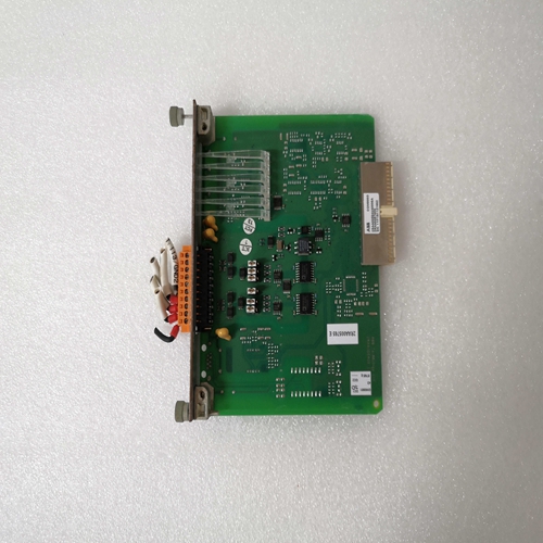
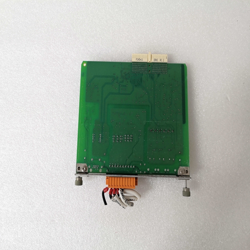
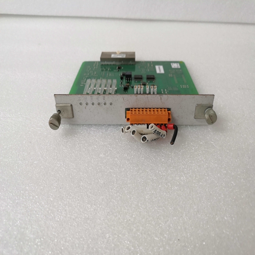
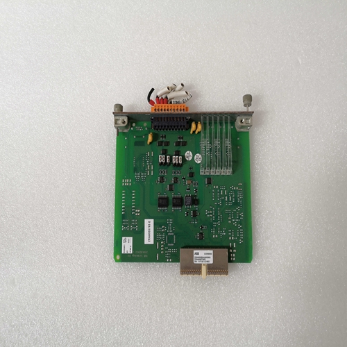
COM0003串行模块卡件
DECS-100通常位于发电机导管箱中。它设计用于面板后面安装,需要一个用于前面板观察的切口。提供的安装硬件包括六个#12螺纹形成螺钉,穿过导管箱中的安装孔并拧入塑料中DECS-100的外壳。钢制安装螺钉的建议扭矩范围为4.07至4.52牛顿米(36至40英寸磅)。该装置必须安装在环境温度变化的地方不超过第1节“一般信息”中规定的允许环境条件,规格。DECS-100包装尺寸如图4-1所示。切口和钻孔尺寸
如图4-2所示。图纸尺寸以英寸和毫米为单位(括号内)。DECS-100连接取决于应用和励磁方案。不正确的接线可能导致装置损坏。检查零件号,以确保您之前拥有正确的装置连接和施加功率。DECS-100终端
DECS-100装置有两种类型的接口端子(图4-3)。一种是四分之一英寸快速连接端子,另一种是9针DB9连接器。所有端子均位于装置后部。
四分之一英寸快速连接端子标签位于壳体后部。表演的电线常见功能,如电压传感引线,应分组在一起。9引脚DB-9型连接器用于与IBM兼容PC和手持计算机的临时接口。
图4-3显示了DECS-100后面板上的端子连接。除非另有说明
如上所述,连接线的最小尺寸应为14 AWG。总线电压感应输入(可选)
总线电压传感端子标记为B1和B3。这些端子仅用于:包括电压匹配选项。母线输入对发电机感应不相位敏感。表4-1
列出总线电压感测的端子分配。发电机电压感应输入
发电机电压感应端子标记为E1、E2和E3。DECS-100配备有:三相感应作为标准。单相感应通过连接C相感应获得端子E2和E3的输入。表4-2列出了三相和单相的端子分配发电机电压感应。
B相线路电流传感输入
通过用户提供的电流互感器(CT)降低发电机线路电流。次要的来自该变压器的电流被施加到标记为CT1和CT2的端子。
辅助输入
附件输入电压端子标记为A和B,并接受±3 Vdc的最大信号。
相对于端子B,施加到端子A的正电压导致激活模式设定点:
增长对于每±1 Vdc的变化,激活模式设定值将实现±10%的变化。
升高和降低触点输入
远程设定点调整可通过连接单极双掷(SPDT)或双掷(SDT)来实现,弹簧复位,中心断开开关连接到标记为6U、7和6D的端子。要连接此开关,中心极或公共端子必须连接到端子7。其他两个端子连接到端子6U和6D。
该远程调节开关可安装在距离DECS-100 150英尺的地方,屏蔽电缆。只能将干燥、不接地的开关触点应用于升高和降低接触输入。
The DECS-100 is normally located in the generator conduit box. It is designed for behind the panel
mounting and requires a cutout for front panel viewing. Supplied mounting hardware consists of six #12
thread-forming screws that pass through mounting holes in the conduit box and thread into the plastic
shell of the DECS-100. The recommended torque range for the steel mounting screws is 4.07 to 4.52
newton-meters (36 to 40 inch-pounds). The unit must be mounted where the ambient temperature does
not exceed the allowable environmental conditions called out in Section 1, General Information,
Specifications. DECS-100 package dimensions are shown in Figure 4-1. Cutout and drilling dimensions
are shown in Figure 4-2. Drawing dimensions are shown in inches and millimeters (in parenthesis). DECS-100 connections are dependent on the application and excitation scheme. Incorrect wiring may
result in damage to the unit. Check the part number to ensure that you have the correct unit before
connecting and applying power. DECS-100 Terminations
DECS-100 units have two types of interface terminals (Figure 4-3). One type is quarter-inch, quickconnect terminals and the other is a 9-pin DB9 connector. All terminals are located on the rear of the unit.
The quarter-inch, quick-connect terminal labels are located on the rear of the case. Wires performing
common functions, such as voltage sensing leads, should be grouped together. The 9-pin DB-9 type
connector is used for temporary interface with both IBM compatible PCs and hand-held computers.
Figure 4-3 shows the terminal connections located on the rear panel of the DECS-100. Except as noted
above, connections should be made with minimum wire size of 14 AWG.Bus Voltage Sensing Inputs (Optional)
The bus voltage sensing terminals are labeled B1 and B3. These terminals are used only on units that
include the Voltage Matching option. The bus input is not phase sensitive to generator sensing. Table 4-1
lists the terminal assignments for bus voltage sensing. Generator Voltage Sensing Inputs
The generator voltage sensing terminals are labeled E1, E2, and E3. The DECS-100 comes equipped for three-phase sensing as standard. Single-phase sensing is obtained by connecting the C-phase sensing input to terminals E2 and E3. Table 4-2 lists the terminal assignments for three-phase and single-phase generator voltage sensing. Phase B Line Current Sensing Input
Generator line current is stepped down through a user-supplied current transformer (CT). Secondary current from that transformer is applied to terminals labeled CT1 and CT2.
Accessory Input
The accessory input voltage terminals are labeled A and B and accept a maximum signal of ±3 Vdc.
Positive voltage applied to terminal A with respect to terminal B causes the active mode setpoint to
increase. For every ±1 Vdc change, a ±10% change in the active mode setpoint is achieved.
Raise and Lower Contact Inputs
Remote setpoint adjustment may be accomplished by connecting a single-pole, double-throw (SPDT),spring return, center-off switch to the terminals labeled 6U, 7, and 6D. To connect this switch, the center pole, or common terminal, must be connected to terminal 7. The other two terminals are connected toterminals 6U and 6D.
This remote adjust switch may be mounted up to 150 feet away from the DECS-100 when using twisted,shielded cable. Only dry, ungrounded switching contacts should be applied to the Raise and Lower
contact inputs.

