


")
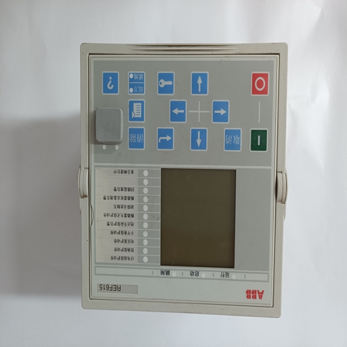
REF615C_C控制触摸屏
来自C相和A相的电压信号
ADC使用发电机的(VC-A)计算发电机跨相电压的均方根值类似地,来自发电机相C和B(VC-B)的电压信号由ADC用于计算C相和B相发电机电压的均方根值。发电机B相的均方根值
微处理器根据C相至A相信号(VC-A)计算A相电压(VB-A),以及相位C到相位B(VC-B)信号。
此外,发电机C相至A相(VC-A)信号应用于滤波过零检测器环行该信号应用于微处理器,用于计算发电机频率。B相线路电流
B相线路电流(IB)信号通过客户提供的电流互感器(CT)产生并通过端子CT1和CT2进行监控。根据所选选项,电流可达1安培(型号xx1)或5安培(型号xx5)rms可在这些端子上进行监测。这个在这些端子处监测的电流由内部电流互感器进行缩放和调节,以及ADC使用的有源电路。应用于ADC的信号用于计算B相线路电流。此外,B相线路电流与C相至A相发电机电压之间的相位角为计算用于下垂和无功/功率因数运行。
附件输入(辅助调整)该输入允许通过应用正或来调整DECS-100调节设定点端子A和B之间的负直流电压。
施加到端子A的正电压
端子B将导致激活模式设定点增加。可将-3至+3 Vdc的电压施加至:这个输入。该电路在直流电源上感应出1000欧姆的负载。±3 Vdc信号的应用对应于设定点的±30%变化。
电压对调节器磁场输出端子F+和F-上的电压(VFIELD)进行监控、定标和在施加到ADC之前进行调节。该信号用于计算磁场电压的直流值用于系统保护。
电流通过主功率输出开关的电流(IFIELD)被转换成比例电压电平。这电压信号在被施加到ADC的输入之前被缩放和调节。结果被使用计算磁场电流的直流值,用于手动操作模式和保护系统。
接触输入电路由内部13 Vdc电源供电的五个触点输入电路从用户提供的隔离干式触点提供输入控制。
提升闭合端子6U和7之间的触点会导致有效工作设定值增加。这只要触点闭合,功能就会激活。
降低闭合端子6D和7之间的触点会导致有效工作设定值降低。这只要触点闭合,功能就会激活。
The voltage signal from phase C and A
(VC-A) of the generator is used by the ADC to calculate the rms value of generator voltage across phases
C and A. Likewise, the voltage signal from phase C and B (VC-B) of the generator is used by the ADC to
calculate the rms value of generator voltage across phases C and B. The rms value of generator phase B
to phase A voltage (VB-A) is calculated by the microprocessor from the phase C to phase A signal (VC-A)and
the phase C to phase B (VC-B) signal.
Additionally, the generator phase C to phase A (VC-A) signal is applied to a filtered, zero-cross detector
circuit. This signal is applied to the microprocessor and is used to calculate generator frequency.
B-Phase Line Current
The phase B line current (IB) signal is developed through a customer supplied current transformer (CT)
and monitored through terminals CT1 and CT2. Depending on the option selected, current up to 1 ampere
(style number xx1) or 5 amperes (style number xx5) rms may be monitored at these terminals. The
current monitored at these terminals is scaled and conditioned by an internal current transformer and
active circuitry for use by the ADC. The signal applied to the ADC is used to calculate the rms value of
phase B line current.
Additionally, the phase angle between phase B line current and phase C to phase A generator voltage is
calculated for use during droop and var/power factor operation.
Accessory Input (Auxiliary Adjust)
This input allows adjustment of the DECS-100 regulation setpoint by the application of a positive or
negative dc voltage across terminals A and B. Positive voltage applied to terminal A with respect to
terminal B will cause the active mode setpoint to increase. Voltage from –3 to +3 Vdc may be applied to
this input. The circuit induces a 1,000-ohm burden on the dc source. The Application of a ±3 Vdc signal
corresponds to a ±30 percent change in setpoint.
Field Voltage
Voltage (VFIELD) across the regulator field output terminals, F+ and F–, is monitored, scaled, and
conditioned before being applied to the ADC. This signal is used to calculate the dc value of field voltage
for use in system protection.
Field Current
Current (IFIELD) through the main power output switch is converted to a proportional voltage level. This
voltage signal is scaled and conditioned before being applied to the input of the ADC. The result is used
to calculate the dc value of field current for use in the Manual mode of operation as well as protection of
the system.
Contact Input Circuits
Five contact input circuits powered from an internal 13 Vdc power supply provide input control from usersupplied, isolated, dry-type contacts.
Raise
Closing a contact across terminals 6U and 7 causes the active operating setpoint to increase. This
function is active as long as the contact is closed.
Lower
Closing a contact across terminals 6D and 7 causes the active operating setpoint to decrease. This
function is active as long as the contact is closed.

