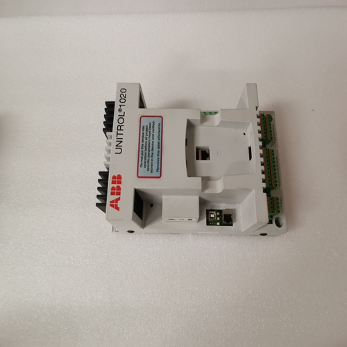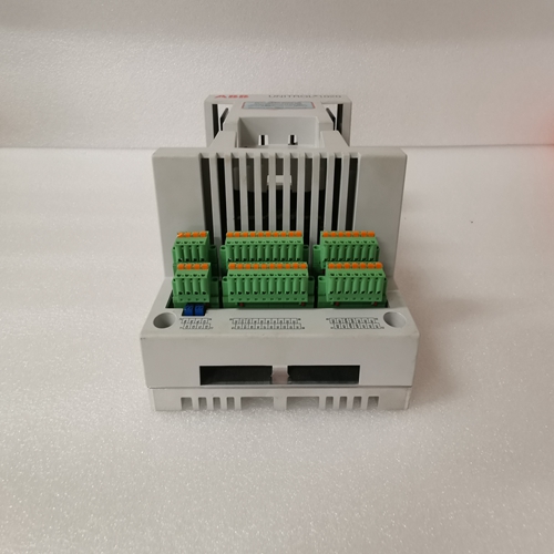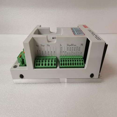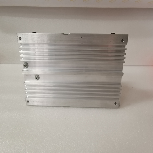
UNS0119A-Z,V1控制处理器
CPX 928是单插槽PLC CPU,即由MS-DOS编程和配置,或要执行的基于Windows的编程软件机器、工艺和材料的实时控制处理系统。它与I/O通信机架安装的智能选件模块背板采用VME C.1标准格式。
支持的选项模块包括LAN接口字母数字可编程协处理器模块
用于IC660/661 I/O的显示协处理器、总线控制器产品、通信模块、I/O链路
接口和所有IC697系列的离散和模拟I/O模块。用户RAM存储器
CPX928具有内置内存板,其中6MB电池支持的CMOS RAM存储器,用于用户数据(程序、配置和寄存器数据)存储用户闪存
CPX928具有256K的内置非易失性闪存用户数据存储器(程序、配置和寄存器数据)存储。该闪存的使用是:
可选择的闪存中的固件存储
该CPU使用闪存存储操作数据系统固件。这允许在不拆卸或更换模块的情况下更新固件EPROM。操作系统固件已更新通过将PC兼容计算机连接到模块的串行端口,并运行所包含的软件使用固件升级套件。
操作、保护和模块状态此模块的操作可由控制三位运行/停止开关或通过附带的编程器和编程软件。
可以锁定程序和配置数据通过软件密码或通过记忆保护钥匙开关。当钥匙在受保护位置、程序和配置数据可以只能由并联的编程器进行更改仅(至总线变送器模块)。a的状态CPU由上的七个绿色LED指示模块前面。
The CPX 928 is a single slot PLC CPU that is
programmed and configured by MS-DOS or
Windows based programming software to perform
real time control of machines, processes and material
handling systems. It communicates with I/O and
smart option modules over the rack-mounted
backplane using the VME C.1 Standard format.
Supported option modules include LAN Interface
modules, Programmable Coprocessor, Alphanumeric
Display Coprocessor, Bus Controller for IC660/661 I/O
products, Communications modules, I/O Link
Interface, and all of the IC697 family of discrete and
analog I/O modules.User RAM Memory
The CPX928 has a built-in memory board with 6
Mbytes of battery-backed CMOS RAM memory for
user data (program, configuration, and register data)
storage.
User Flash Memory
The CPX928 has 256K of built-in, non-volatile flash
memory for user data (program, configuraton, and
register data) storage. Use of this flash memory is
optional.
Firmware Storage in Flash Memory
This CPU uses flash memory for storing the operating
system firmware. This allows firmware to be updated without disassembling the module or replacing
EPROMs. The operating system firmware is updated
by connecting a PC compatible computer to the module’s serial port and running the software included
with the firmware upgrade kit.
Operation, Protection, and Module Status
Operation of this module can be controlled by the
three-position RUN/STOP switch or remotely by an
attached programmer and programming software.
Program and configuration data can be locked
through software passwords or manually by the
memory protect keyswitch. When the key is in the
protected position, program and configuration data can
only be changed by a programmer connected parallel
only (to the Bus Transmitter module). The status of a
CPU is indicated by the seven green LEDs on the
front of the module.


