


")
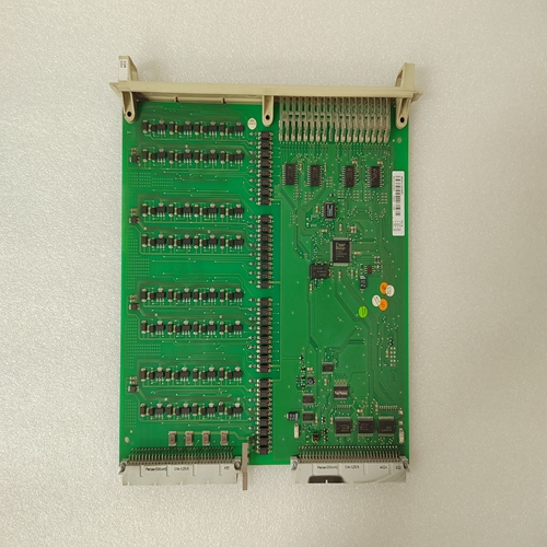
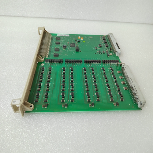
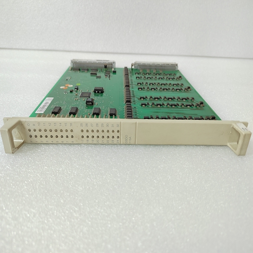
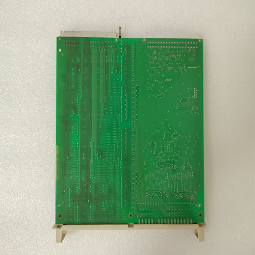
DSDO115A信号输出模块
同步I/O扫描
如果需要周期性地处理一组一致的输入数据,同步I/O需要扫描。可以为FIP定义多达15个同步扫描集总线控制器。
在同步I/O扫描模式下,PLC CPU执行同步应用程序
FIP总线控制器完成所有输入消耗后的程序
同步扫描集中的数据和验证程序。FIP总线控制器触发
PLC CPU和CPU调度指定的应用程序。
PLC CPU扫描PLC参考表中的扫描集输入,以及程序开始。在逻辑结束时,PLC CPU执行输出扫描(如果已配置)。为了正确操作,程序应完成逻辑并执行输出扫描在FIP总线控制器被调度以产生到网络的输出之前。
有关计时的更多详细信息,请参阅重要产品信息文件,GFK-1200。
下图显示了典型同步的定时特性应用在此示例中,单个同步扫描集被配置为包含时隙DI和DO。
离散输入传输时隙:包含输入的定义传输时隙
同步扫描集的数据。允许PLC应用程序的最长时间
输入时隙被配置在比输出时隙早但邻近输出时隙的相位。
离散输出传输时隙:定义的传输时隙,包含同步扫描集的输出数据。为了允许PLC应用程序的最长时间,输出时隙配置在比输入时隙。
FBC消耗延迟:调度消耗之前FBC中的固定延迟
输入TVAs。该时间固定为1ms。
DI时隙中TVA的FBC消耗:从并将单个TVA传输到双端口存储器。长度时间取决于COMV和TVA的数量和长度。
Synchronous I/O Scanning
If it is necessary to periodically process a coherent set of input data, synchronous I/O
scanning is required. It is possible to define up to 15 synchronous scan sets for the FIP
Bus Controller.
In Synchronous I/O Scanning mode, the PLC CPU executes a synchronous application
program after the FIP Bus Controller has completed the consumption of all of the input
data and validators in the synchronizing scan set. The FIP Bus Controller triggers the
PLC CPU and the CPU schedules the specified application program.
The PLC CPU scans the scan set inputs into the PLC reference tables, and the program
starts. At the end of the logic the PLC CPU performs the output scan, if one is configured.
For proper operation, the program should complete the logic and perform the output scan
before the FIP Bus Controller is scheduled to produce the outputs to the network.
For more detailed information about timing, please refer to the Important Product
Information document, GFK-1200.
The illustration below represents the timing characteristics of a typical synchronous
application. In this example, a single synchronous scan set is configured to contain the
time slots DI and DO.
Discrete Input Transport Time Slot: The defined transport time slot containing the input
data for the synchronous scan set. To allow the maximum time for the PLC application
program, the input time slot is configured at a phase earlier than but adjacent to the output time slot.
Discrete Output Transport Time Slot: The defined transport time slot containing the
output data for the synchronous scan set. To allow the maximum time for the PLC application program, the output time slot is configured at a phase later than but adjacent to
the input time slot.
FBC Consumption Delay: A fixed delay in the FBC before scheduling the consumption
of the input TVAs. This time is fixed at 1ms.
FBC Consumption of TVAs in DI time slot: The time necessary to read the COMVs from
the network and transfer the individual TVAs to the dual–port memory. The length of
time depends on the number and length of the COMVs and TVAs.

