


主营产品
PLC可编程控制器模块,DCS卡件,ESD系统卡件,振动监测系统卡件,汽轮机控制系统模块,燃气发电机备件等,优势品牌:Allen Bradley、BentlyNevada、ABB、Emerson Ovation、Honeywell DCS、Rockwell ICS Triplex、FOXBORO、Schneider PLC、GE Fanuc、Motorola、HIMA、TRICONEX、Prosoft等各种进口工业零部件
产品广泛应用于冶金、石油天然气、玻璃制造业、铝业、石油化工、煤矿、造纸印刷、纺织印染、机械、电子制造、汽车制造、塑胶机械、电力、水利、水处理/环保、锅炉供暖、能源、输配电等等
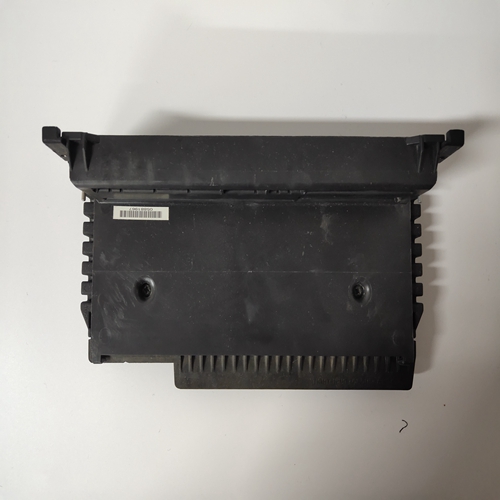
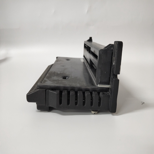
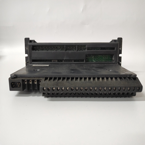
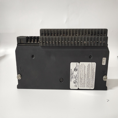
IC660TBD024K燃机控制模块
❑ 仅当操作员激活启用开关及时识别危险情况,以便可以立即采取必要措施避免此类情况!
❑ 启用开关仅用于启用执行以下操作的命令:危险的运动。命令本身必须被激活
通过单独的操作元件(HT上的键)。只有以下人员:允许激活启用开关,也允许在这是一个危险的地区。
❑ 2位启用开关只能与紧急停止设施。
❑ 在HT 40X上,启用开关始终具有2个通道。能够评估在以下方面应遵守哪些规则或规则的哪些部分:机器的安全相关部件,可进行风险评估。
2.4机械风险评估对于风险评估,必须采用以下标准:
❑ EN 292“机械设计的一般原则”
❑ EN 1050“机械风险评估原则”
❑ EN 954-1“控制系统的安全相关部件”
安全类别(B、1、2、3、4)最终定义了此风险评估的机器结果。
以下接线图显示了如何使用KEBA实现安全等级3
手持终端及其安全相关部件。机器的整个概念必须是:根据安全类别3的原则制定。功能程序:
仅当两个启用开关ZT1和ZT2“同时”激活两个输出继电器K1时并且K2将通电并且输出触点13-14和23-24将闭合。如果出现以下情况,输出继电器K1和K2将不会通电:
•仅激活一个启用开关,
•超过同时期,
•反馈控制回路X1-X2开路。
如果启用开关在同时激活后被释放,则输出继电器K1和K2将再次断电。强制引导输出触点13-14和23-24将断开。输出只有在两个启用开关同时释放后,继电器才会再次通电再次操作。
通过这种方式,使能开关满足要求,即避免一个单一错误
使安全功能不可操作。最迟将在下一个周期识别单个错误。
❑ Enabling switches may only be used if the operator activating the
enabling switch recognizes the dangerous situation in time so that he
can immediately take the necessary measures to avoid such situations!
❑ The enabling switch is only used to enable commands for performing
dangerous movements. The commands themselves must be activated
by a separate operating element (key on HT). Only persons who are
allowed to activate the enabling switch are also allowed to work in the
dangerous area.
❑ 2-position enabling switches may only be used in connection with an
emergency stop facility.
❑ At the HT 40X, the enabling switches always feature 2 channels.
To be able to assess what rules or what parts of the rules are to be observed regarding the
safety-related parts of a machine, the risk assessment can be carried out.
2.4 Risk Assessment of Machinery
For the risk assessment the following standards must be applied:
❑ EN 292 „General principles for design of machinery“
❑ EN 1050 „Principles for risk assessment of machinery“
❑ EN 954-1 „Safety-related parts of control systems“
The safety categories (B, 1, 2, 3, 4) which finally define the structure of safety-related parts of
a machine result from this risk assessment.
The following wiring diagram shows how the safety category 3 can be fulfilled with KEBA's
handheld terminals and their safety-related parts. The entire concept of the machine must be
laid out according to the principles of safety category 3.Functional procedure:
Only if both enabling switches ZT1 and ZT2 are activated „simultaneously“ both output relays K1
and K2 will energise and the output contacts 13-14 and 23-24 will close.
The output relays K1 and K2 will not energise if
• only one enabling switch is activated,
• the simultaneity period is exceeded,
• the feedback control loop X1-X2 is open.
If an enabling switch is released after being simultaneously activated, the output relays K1 and K2
will de-energise again. The forced-guided output contacts 13-14 and 23-24 will open. The output
relays will energise again only after both enabling switches have been released and simultaneously
operated once again.
In this way the enabling switches meet the requirement which consists in avoiding that one single error
makes the safety function inoperational. A single error will be recognized at the next cycle at the latest.

