


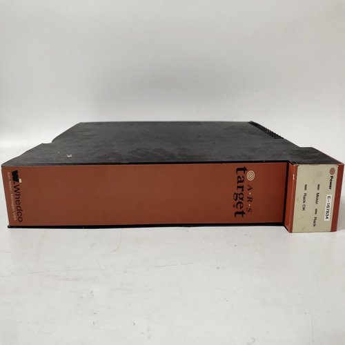
GE TARGET 78004654模块
可拆卸配置板
可移动配置板(RCB)可以安装在此控制器16中。它保留了安装RCB的控制器使用的配置。如果该控制器发生故障,RCB可以:已卸下并安装在替换控制器中。然后,可以将存储的配置选择为活动配置控制器中的配置。通电后,控制器将测试RCB,并将RCB中存储的配置与控制器的配置进行比较配置如果RCB通过所有测试且配置相同,控制器将正常通电并使用来自MPU板的配置。如果检测到问题或配置不同,将显示联机状态或脱机错误消息。有关信息,请参阅维护部分。
9.5实时时钟/配置备份板
控制器具有可选的实时时钟和配置备份板17
备份执行与上述RCB相同的功能。此外,该板还包括一个实时时钟。
可以使用STATN参数中的内置时钟功能块设置时间。它也可以设置在Modbus、LIL或以太网。
10.0控制器和系统测试
本节介绍了一系列步骤,以验证控制器的操作,并帮助用户熟悉
控制器的功能。新的控制器出厂时配置为出厂配置
选项FCO101单回路控制器或用户指定的自定义配置。以下程序适用于:
具有出厂设置参数值的FCO101。如果安装了自定义配置,或者如果已配置
控制器,可能需要修改程序以测试该配置中的所有功能块。
要确定控制器的当前配置,请执行以下任一操作:
•请参阅该控制器的配置文档
•将配置上传到运行图形配置软件的PC上,其中可以进行配置查看
•进入配置模式,逐步完成配置,记录配置的功能块和
输入的参数值
在以下步骤中,“按下”表示面板按钮(键)。
10.1控制器配置和测试
本节的目的是配置和测试控制器,并让用户熟悉控制器的
面板按钮、脉冲发生器和显示器。本节还介绍了几个配置主题。
10.1.1连接和电源
1.将电源连接到控制器。型号参考控制器铭牌,然后参考第14节
本手册适用于电源要求。有关连接,请参阅第8节“安装”。
REMOVABLE CONFIGURATION BOARD
The Removable Configuration Board (RCB) can be installed in this controller16. It retains a complete copy of the
configuration being used by the controller in which the RCB is installed. Should that controller fail, the RCB can be
removed and installed in the replacement controller. The stored configuration can then be selected as the active
configuration in the controller.
On power up, the controller will test the RCB and compare the configuration stored in the RCB to the controller’s
configuration. If the RCB passes all tests and the configurations are identical, the controller will power up normally
and use the configuration from the MPU board. If a problem is detected or the configurations are different, an ONLINE STATUS or OFF-LINE ERROR message will be displayed. See the Maintenance section for messages.
9.5 REAL TIME CLOCK/CONFIGURATION BACKUP BOARD
The controller is available with an optional real time clock and configuration backup board17. The configuration
backup performs the same functions as the RCB described above. In addition, the board includes a real time clock.
The time can be set using the built-in CLOCK function block in the STATN parameters. It can also be set over the
Modbus, LIL, or Ethernet network.
10.0 CONTROLLER AND SYSTEM TEST
This section presents a series of steps to verify controller operation and to help a user become familiar with the
functionality of the controller. A new controller is shipped factory configured with either Factory Configured
Option FCO101 Single Loop Controller or a user-specified custom configuration. The following procedure is for
FCO101 with factory set parameter values. If a custom configuration was installed, or if you have configured the
controller, it may be necessary to modify the procedure to test all function blocks in that configuration.
To determine the current configuration of a controller, either:
• refer to your configuration documentation for that controller
• upload the configuration to a PC running the Graphical Configuration Software where the configuration can be
viewed
• enter the configuration mode and step through the configuration recording the configured function blocks and
entered parameter values
In the following steps, ‘press’ indicates a faceplate button (key).
10.1 CONTROLLER CONFIGURATION AND TEST
The purpose of this section is to configure and test the controller and to familiarize the user with the controller’s
faceplate pushbuttons, pulser, and displays. This section also introduces several configuration topics.
10.1.1 Connections and Power
1. Connect power to the controller. Refer to Controller nameplate for model number and then to Section 14 of
this manual for power requirements. Refer to Section 8 Installation for connections.

