


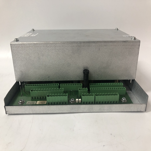
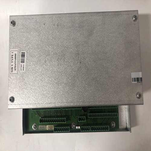
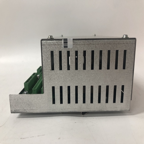
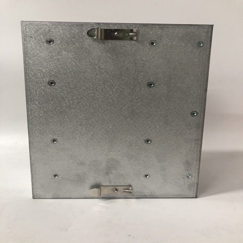
ABB 0504994880 机器人稳压模块
安装:1.使用刀片宽度为1/8“的一字螺丝刀,分别转动未使用的端子螺钉顺时针旋转,直到刚好拧紧-不要过度拧紧
2.阅读要插入的连接器上的字母/数字,并参考连接器位置的相邻图。每个连接器是:键入适当的插件位置。
3.目视检查连接器插座中的所有12个引脚是否笔直。如果销仅轻微弯曲,可以尝试非常温和的矫直。
过度矫直可能导致销断裂,需要:更换连接器插座。
4.将连接器与连接器插座中的针脚对齐并推动连接器笔直插入。参见下图。
5.两对矩形翼片从盖延伸。安装盖子通过将从盖的一侧延伸的一对凸耳安装到一对端子中的两个矩形槽。现在,压缩稍微U形挤压,然后将另一对盖板凸耳装入剩余一对端子中的槽。
盖可以用两个螺钉固定。
盖子上的孔对齐连接器插座组件中有孔。使用3-48 x¼长或M2.5 x 6长螺钉,用于固定盖子。
8.3.2面板和机架安装指南
面板表面应提供平坦且刚性的安装表面。如果存在以下情况,则加固面板背面:面板表面弯曲的可能性。电缆管道、导管和布线不应干扰拆除或仪表、控制装置、报警器和相关设备的可接近性。
8.3.3车站安装
拧紧两个安装夹螺钉时,需要一个柄部至少为10“(254 mm)的直槽螺丝刀。
1.找到提供的安装夹套件。它包含两个安装夹和两个8-32 x 1”凹头螺钉。
将安装螺钉拧入安装夹。参见图8-6。
2.从面板前面,将控制器外壳插入面板切口。
3.轻轻旋转顶部安装夹,将其安装到壳体切口中。然后,拉直卡子并部分拧紧安装螺钉。插入、拉直并部分拧紧底部卡子。
4.将控制器与面板对齐。
5.交替拧紧顶部和底部安装夹螺钉,直到控制器固定到面板上。不要过度拧紧和扭曲外壳。8.4电气安装
这些章节包含Moore 353接线的电气连接细节。每种情况下的后连接器和端子被识别。第8.3节机械安装中讨论了连接器类型。连接器盖拆卸和描述了固定部分或连接器与可移除部分的分离。
第8.4.2节接线指南包含有关接线连接器拆卸、导线尺寸、导线的具体信息布线时需要的剥离和其他细节。在开始连接控制器之前,请阅读本节。第8.4.3节至第8.2.12节包含接线图,以及必要时的分步安装程序,以:
描述I/O和网络布线。第8.4.13节提供了电源输入接线信息。单控制器和示出了菊花链电源布线。
Installation:
1. Using a straight blade screwdriver with a 1/8" blade width, turn each
unused terminal screw clockwise until it is just tight - do not over
tighten.
2. Read the letters/numbers on the connector to be inserted and refer to
the adjacent figure for the connector location. Each connector is
keyed for the appropriate plug-in location.
3. Visually check that all 12 pins in the Connector Socket are straight.
If a pin is only slightly bent, very gentle straightening can be tried.
Excessive straightening may cause the pin to break requiring
replacement of the Connector Socket.
4. Align the connector with the pins in the Connector Socket and push
the connector straight in. See the adjacent figure.
5. Two pairs of rectangular tabs extend from the cover. Install the cover
by fitting one pair of tabs extending from one side of the cover into
two of the rectangular slots in a pair of terminals. Now, compress the
U-shaped extrusion slightly and fit the other pair of cover tabs into
the slots in the remaining pair of terminals.
6. The cover can be secured with two screws. Holes in the cover align
with holes in the connector socket assembly. Use 3-48 x ¼ long or
M2.5 x 6 long screws to secure the cover.
8.3.2 Panel and Rack Mounting Guidelines
The panel face should provide a flat and rigid mounting surface. Reinforce the back of the panel if there is a
possibility that the panel face will bow. Raceways, conduit, and wiring should not interfere with the removal or
accessibility of the instruments, control devices, alarms, and related equipment.
8.3.3 Station Mounting
A straight slot screwdriver with at least a 10" (254 mm) shank is needed to tighten the two mounting clip screws.
1. Locate the supplied Mounting Clip Kit. It contains two mounting clips and two 8-32 x 1" fillister head screws.
Thread the mounting screws into the mounting clips. See Figure 8-6.
2. From in front of the panel, insert the controller case into the panel cutout.
3. Slightly rotate the top mounting clip to fit it into the case cutout. Then straighten the clip and partially tighten
the mounting screw. Insert, straighten and partially tighten the bottom clip.
4. Square the controller with the panel.
5. Alternately tighten top and bottom mounting clip screws until the controller is secured to the panel. Do not
over tighten and distort the case. 8.4 ELECTRICAL INSTALLATION
These sections contain electrical connection details for wiring a Moore 353. Each case rear connector and terminal
is identified. Connector styles are discussed in section 8.3 Mechanical Installation. Connector cover removal and
separation of the fixed portion or a connector from the removable portion is described.
Section 8.4.2 Wiring Guidelines contains specific information about connector removal for wiring, wire size, wire
stripping and other details that will be needed while wiring. Read this section before beginning to wire a controller.
Sections 8.4.3 through 8.4.12 contain wiring diagrams and, where needed, step-by-step installation procedures to
describe I/O and network wiring. Section 8.4.13 provides power input wiring information. Single controller and
daisy chained power wiring are illustrated.

