


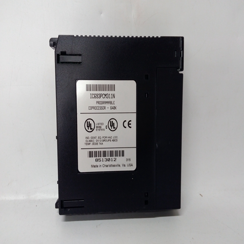
IC693PCM311数字燃机模块
要安装端子盖:
1.如图所示定位盖。注意四个钩子接线片和以太网电缆间隙断路器。
2.在两个小切口处轻轻挤压盖在盖子边缘,并完全插入四个钩子后面板插槽中的盖舌。
3.让盖侧放松。把盖子拉直直到它卡入位。在盖边缘将接合上的两个对齐凸舌后面板。
需要时,以太网电缆应退出通过盖中的大切口。
要卸下盖子:
1.在两个切口处轻轻挤压盖
在盖边缘中(距离盖的顶部)并向上推盖。
2.从后面板上拉出盖。安装或取下盖子:
挤压双方~1/16"清除对齐标签。
以太网电缆断路器。
图8-1直接入口连接器,盖的安装和拆卸安装
1.将连接器的可拆卸部分与固定部分对齐。
2.将可拆卸部分压到固定部分上。
3.拧紧两个固定螺钉。不要过紧。检查导线和部件是否保持连接安全地。
4.如上图所示安装盖。
盖和连接器的拆卸和安装,侧面进入删除:
1.轻轻压缩连接器盖的U形挤压件,以释放连接器盖的凸耳,从而拆下连接器盖。
盖可以用两个螺钉固定,如下所述。盖子如图8-5所示。
2.如有必要,断开、松开或解开连接至待拆卸连接器的导线。一定要去导线是否有足够的松弛度,以便拆卸接头。
3.抓住连接器凸舌,并从壳体中直接拉出。拉向中心的轻微偏压
连接器插座通常易于拆卸。参见图8-3。注意不要应力或损坏连接的导线和组件。
To Install Terminal Cover:
1. Orient the cover as shown. Note the four hooked
tabs and Ethernet cable clearance cutout.
2. Squeeze the cover slightly at the two small cutouts
in the cover edges and fully insert the four hooked
cover tabs in the rear panel slots.
3. Allow cover sides to relax. Pull the cover straight
down until it snaps into place. The cutouts in the
cover edges will engage two alignment tabs on
the rear panel.
Where needed, the Ethernet cable should exit
through the large cutout in the cover.
To Remove Cover:
1. Squeeze the cover slightly at the two cutouts
in the cover edges (about 2" down from the
top of the cover) and push cover upward.
2. Pull cover out from rear panel.
To install or
remove cover:
squeeze
both sides
~1/16"
to clear
alignment
tabs.
Ethernet cable cutout.
FIGURE 8-1 Direct Entry Connectors, Cover Installation and Removal
Installation
1. Align the removable portion of the connector with the fixed portion.
2. Press the removable portion onto the fixed portion.
3. Tighten the two captive screws. Do not over tighten. Check that wires and components remain connected
securely.
4. Install the cover as shown in the above figure.
COVER AND CONNECTOR REMOVAL AND INSTALLATION, SIDE ENTRY
Removal:
1. Remove the connector cover by slightly compressing the cover’s U-shaped extrusion to free the cover’s tabs.
The cover may be secured by two screws, as described below. The cover is shown in Figure 8-5.
2. As necessary, disconnect, unclamp, or unbundle wires connected to the connector to be removed. Be sure there
is sufficient slack in the wiring for connector removal.
3. Grasp the connector tab and pull straight out from the case. A slight bias on the pull toward the center of the
Connector Socket will often ease removal. See Figure 8-3. Be careful not to stress or damage connected wires
and components.

