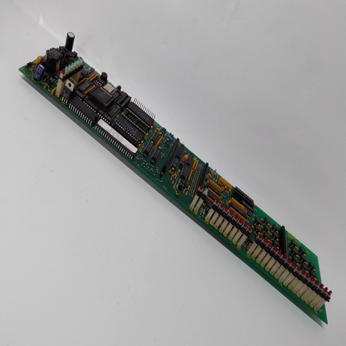
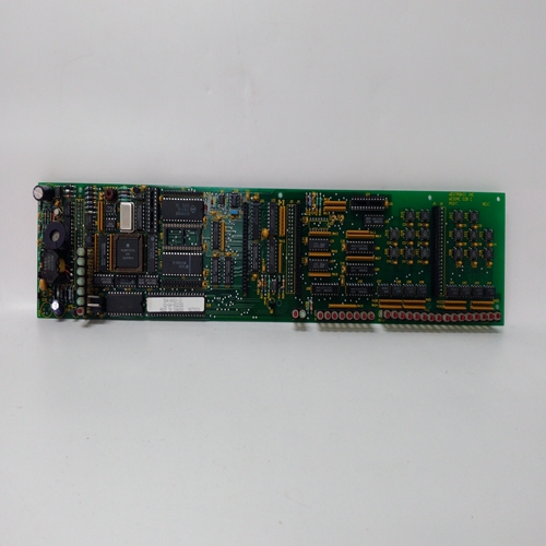
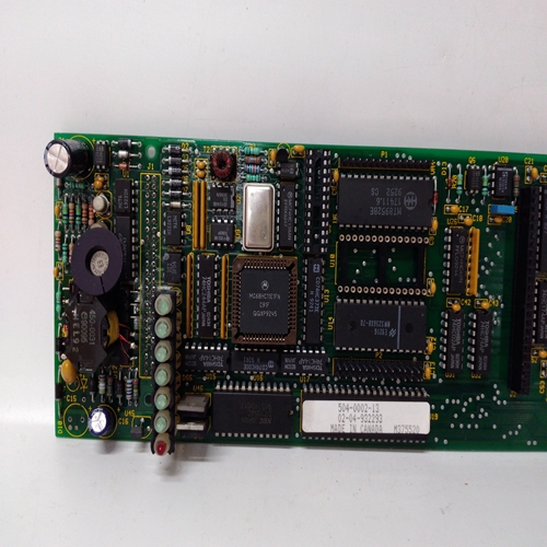
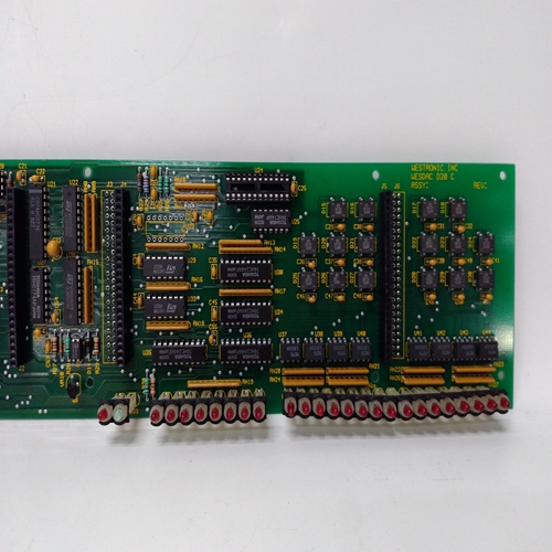
WESDAC D20 C模块
跟踪命令输入TC,断言为高(1),导致用于跟踪输入变量TV的比率块然后,重新计算的比值为R=TV/(A xE) 。R值将限制在高或低限制范围设置。的出厂默认设置比率限制为0.00-30.00。
可以使用快速设置调整比率如果参数“快速设置”设置为“是”,则为功能。这个比例将随着旋钮的转动而不断变化调整。达到最终值时,按下存储按钮,以确保新的比率设置为:保持在冷通电状态。QS DPP参数启用比率调整分辨率的设置当处于快速设置模式时。
如果输入A或E未配置,其值将设置为1。如果输入TC或TV未配置,则其值将设置为0。
TO(跟踪输出)通常用于使用外部设备在中设置比率的应用中替换比率参数(然后将R设置为1.0)。当需要具有比率块轨迹的输出时外部设备被迫跟踪到的TV变量。
输入E将等于TV/[Ax(1.0)],因此比率块输出O1将等于TV。当包含比率功能块的配置在i|config中编辑,然后下载到在线控制器,控制器将忽略比率参数值的变化,并继续以预加载值RCT_运行。功能块提供重复时间循环,可以用于逻辑定时操作或PID块,以:提供由PID块控制的自适应接通时间。输出ET将提供以下时间(以分钟为单位):在当前循环(开+关)期间经过。输出RT是当前循环中的剩余时间,将等于定时器未启动时的总循环时间(开+关)起动。
对于固件1.30及更高版本,开启和关闭时间为可在显示器的整个范围内进行调整,即:0.00000到9999999。在早期固件中,最短时间设置为0.1。如果延迟时间设置为小于扫描站的时间延迟时间将等于扫描时间。输入S被断言为高(1),将导致RCT块开始计时循环。输出O1将首先在时间由ON时间设置,然后在由OFF时间设置的时间内它将变低(0)。它将继续重复这个循环直到输入S被断言为低(0),这迫使O1为低(O)并结束定时周期。
Track Command input TC, asserted high (1), causes
the ratio block to track the input variable TV. The
ratio value to be recalculated is then R = TV / (A x
E). The value of R will be limited at the HI or LO
LIMIT range settings. The factory default settings of
the ratio limits are 0.00 - 30.00.
The RATIO can be adjusted using the QUICKSET
feature if parameter QUICKSET is set to YES. The
RATIO will continuously change as the knob is
adjusted. Press the STORE button when the final value is reached to insure that the new RATIO setting will be
retained on a Cold power up condition. The QS DPP parameter enables setting of the Ratio adjustment resolution
when in the QUICKSET mode.
If input A or E is not configured, it’s value will be set to 1. When input TC or TV is not configured, it’s value will
be set to 0.
The TO (Tracked Output) is normally used in applications where an external device is being used to set a ratio in
place of the RATIO parameter (R is then set to 1.0). When it is desired to have the output of the RATIO block track
the TV variable, the external device is forced to track TO. Input E will then equal TV/[Ax(1.0)] and, therefore, the
RATIO block output O1 will equal TV. When a configuration containing the RATIO function block is edited in i|config and then downloaded to an on-line
controller, the controller will ignore a change to the RATIO parameter value and continue to run with the predownload value RCT_ function blocks provide repeat time cycles that can
be used in logic timing operations or with PID blocks to
provide adaptive on times controlled by the PID block.
Output ET will provide the time in minutes that has
elapsed during the current cycle (ON + OFF). Output RT
is the remaining time in the current cycle and will equal the
total cycle time (ON + OFF) when the timer has not been
started.
With firmware 1.30 and higher, the ON and OFF TIME is
adjustable over the full range of the display which is
0.00000 to 999999. In earlier firmware, the minimum time
setting was 0.1. If the delay time is set to less than the scan
time of the station the delay time will equal the scan time.
Input S, asserted high (1), will cause the RCT block to start the timing cycle. Output O1 will first go high (1) for a
time set by ON TIME and then it will go low (0) for a time set by OFF TIME. It will continue to repeat this cycle
until input S is asserted low (0) which forces O1 low (0) and ends the timing cycle.


