


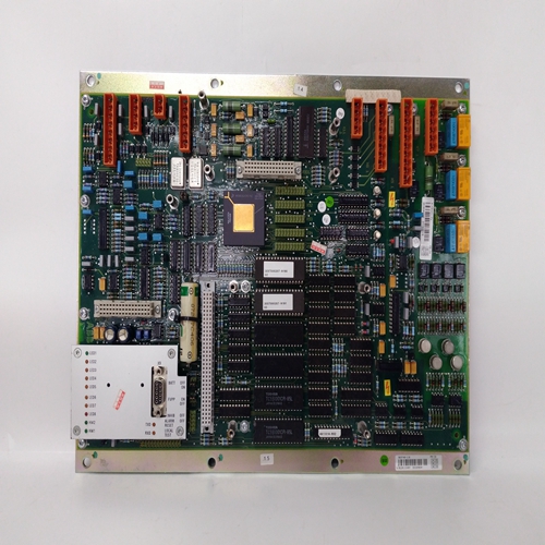
61430001-FU变送器输入卡件
相位通信PCOM功能块,在固件1.30及更高版本,每个循环一个实现更高级别通信的基础设备,如运行批处理管理的PC软件程序。当控制器配置为结构化的,使得逻辑操作在小相位操作,PCOM块便于控制整个相位的逻辑之间的接口批处理的操作和执行每个阶段的控制逻辑。
PCOM块执行的逻辑详见图3-1中的布尔形式。网络通信可以是Modbus或LIL(本地仪表链路)。
详细信息在网络通信中列出部分在ODC或ODS中配置的循环
循环的功能块确定Modbus中的状态字和状态线圈映射。通信状态表示为图3-1,下一页,使用所示符号
在下面Modbus状态映射到线圈和LIL中映射到两个16位状态字的状态,如图所示在下面三个全局通道用于发送两个状态字和一个1-7的整数值表示PCOM块的状态:1=中止,2=完成,3=保持,4=运行,5=INTRLK,6=就绪,7=应急或。第一个通道的位置为:使用LIL CHAN参数配置,由LIL映射表中的通道z表示。
读/写状态R 0W1W0
开始读取状态运行R1/0每个通信状态被读取为1或0。使用Modbus,写入1(W1)或0(W0)将影响
图3-1中相关逻辑定义的通信状态。W1或W0相当于或上的掩码使用LIL命令屏蔽。除OK、RD、RN和HE外,所有未配置的输入将被视为低(0)其将被视为高(1)。三种输出状态,EO(“EMERG”)、IK(“INTRLK”)和FD(“失败”)可配置为优先级0-5。这将影响闪烁等。如前所述,其他控制器状态条件。这些状态也有未确认位,如状态字2.条件中所述可以通过使用本地面板确认按钮或通过写入来确认需要确认的
单个未确认位或未确认PCOM位。
The Phase Communication PCOM function block, in
firmware 1.30 and higher, is available on a one per loop
basis to enable communication with a higher level
device, such as a PC running a batch management
software program. When the controller configuration is
structured such that logic operations are partitioned in
small phase operations, the PCOM block facilitates the
interface between the logic controlling the overall phase
operations for the batch and the logic performing the
control logic for each phase.
The logic performed by the PCOM block is detailed in
Boolean form in Figure 3-1. Network communication
can be either Modbus or LIL (Local Instrument Link).
Details are listed in the Network Communications
section. The LOOP # configured in the ODC or ODS
function block for the loop determines the location of
the status word and the status coils in the Modbus
mapping. Communication states are represented in
Figure 3-1, on the next page, using the symbols shown
below. Modbus states are mapped in coils and LIL
states mapped into two 16-bit status word as shown
below. Three global channels are used to send out the
two status words and an integer value from 1-7 that
represents the status of the PCOM block: 1=ABORTED,
2=DONE, 3=HELD, 4=RUN, 5=INTRLK, 6=READY, 7=EMER OR. The location of the first channel is
configured using the LIL CHAN parameter, represented by channel z in the LIL mapping tables.
Read/Write States R 0
W 1
W 0
START Read States RUN R 1/0
Each communication state is read as a 1 or 0. Using Modbus, a write of a 1 (W1) or a 0 (W0) will affect the
communication state as defined by the associated logic in Figure 3-1. The W1 or W0 is equivalent to a Mask ON or
a Mask OFF using LIL commands. All unconfigured inputs will be treated as low (0) except OK, RD, RN and HE
which will be treated as high (1). Three of the output states, EO (“EMERG”), IK (“INTRLK”), and FD
(“FAILED”) can be configured for priorities 0-5. This will affect the flashing, etc. as previously described for other
controller status conditions. These states also have unacknowledged bits as detailed in status word 2. Conditions
that require acknowledging can be acknowledged by either using the local faceplate ACK button or by writing to
the individual not acknowledged bit or the Not Ack’d PCOM bit.

