


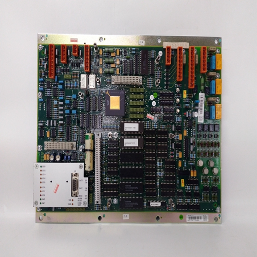
DCC2390A电压监视输入卡件
输入E断言高(1)将启用块输出;当低(0)时,所有输出将设置为低(0)。
进程范围指针参数指向具有范围缩放的另一个功能块,例如模拟提供过程变量的输入。这使控制器能够规范化过程输入的范围。如果未配置此参数,控制器将使用0.0-100.0的范围缩放。
通电-在热启动期间,输出和比较器功能将在通电前的状态下初始化并且所有动态元素将在第一次扫描时在当前输入处初始化。在冷启动期间,所有输出和比较器状态将设置为零,由块功能激活。所有动态元素将
在第一次扫描时在当前输入处初始化。ORSL功能块在每个循环一个的基础上使用并且它们启用主输入信号,例如输出以被其它信号覆盖。为了选择器配置为LO,功能块输出
主输入或超控输入中的较低者。对于选择器配置为HI,功能块将输出较高主输入或超控输入。超驰信号可以是:硬限制,来自等待块或信号来自其他控制器。块超驰输入1和2 can用作HI或LO选择器功能。
附加的通过连接这些,可以适应超驰输入信号选择器(SEL)块的输入。
当ORSL块的输出不是主要输出时输入时,输出OS将为高(1)。此外阻塞会导致操作员面板显示:
当选择了高于0(默认值)的优先级时,“覆盖”状态。如果未配置超驰输入,单个选择器将输出其他输入。当没有输入时:配置后,块将输出0.0,操作系统状态将设置为低(0)。OST_功能块为
当输入P消失时,由接通时间设置的预定时间
高(1)。如果输入P变低(0),输出将保持不变直到时间到期。如果输入P在
准时,如果重试,将重新触发经过的计时器设置为“是”。
对于firmware1.30及更高版本,开启时间可调在整个显示范围内,从0.00000到
9999999。在早期版本中,最短时间设置为0.1。如果延迟时间设置为小于扫描时间
延迟时间将等于扫描时间。
输出ET(经过时间)将从0.0渐变到接通时间值,并保持在该值,直到P变为低(0)。
输出RT(剩余时间)等于接通时间-ET。
通电-在热启动期间,当PU LAST设置为“是”时,模块将在输入/输出状态下初始化
以及在断电发生的瞬间有效的经过时间。冷启动将初始化输入/输出状态,以及已用时间为0。
Input E asserted high (1) will enable the block outputs; when low (0) all outputs will be set low (0).
The process range pointer parameter points to another function block that has range scaling, such as the analog
input that is providing the process variable. This enables the controller to normalize the tuning parameters for the
range of the process input. If this parameter is not configured, the controller will use a range scaling of 0.0 - 100.0.
POWER UP - During a warm start, outputs and comparator functions will be initialized at the state prior to power
down and all dynamic elements will be initialized at the current input on the first scan. During a cold start all
outputs and comparator states will be set to zero, to be activated by the block functions. All dynamic elements will
be initialized at the current input on the first scan. ORSL function blocks are used on a one per loop basis
and they enable a primary input signal, such as the output
from a controller, to be overridden by other signals. For a
selector configured as LO, the function block outputs the
lower of the primary or override inputs. For a selector
configured as HI, the function block will output the higher
of the primary or override inputs. Override signals can be
hard limits, coming from HOLD blocks, or signals coming
from other controllers. Block override inputs 1 and 2 can
be used as HI or LO selector functions. Additional
override inputs can be accommodated by connecting these
inputs to signal selector (SEL) blocks.
When the output of the ORSL block is not the primary
input, the output OS will be high (1). In addition, the
block can cause the operator faceplate to display
‘OVERRIDE’ status when a priority level higher than 0, the default, has been selected.
If an override input is not configured the individual selector will output the other input. When no inputs are
configured, the block will output 0.0 and the OS status will be set low (0). OST_ function blocks provide a high (1) output for a
predetermined time, set by ON TIME, when input P goes
high (1). If input P goes low (0), the output will remain
high until the time expires. If input P goes high during the
on time, the elapsed timer will be re-triggered if RETRIG
is set to YES.
With firmware1.30 and higher the ON TIME is adjustable
over the full range of the display which is 0.00000 to
999999. In earlier versions, the minimum time setting
was 0.1. If the delay time is set to less than the scan time
of the station the delay time will equal the scan time.
Output ET (elapsed time) will ramp from 0.0 to the value of ON TIME and remain there until P goes low (0).
Output RT (remaining time) equals ON TIME - ET.
POWER UP - During a warm start, when PU LAST is set to YES, the block will initialize at the input/output states
and elapsed time in effect at the instant power down occurred. A cold start will initialize the input/output states and
elapsed time to 0.

