


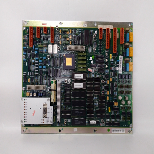
DTCC901B输入接线卡件
当循环事件激活时,输出LE为高(1)。输出SE为站错误激活时为高。6.循环#(在版本1.21固件中,此参数为MB索引,但它们具有相同的功能)。它将用于索引Modbus参数的读取和写入。LIL有25个参数:C1S、C2S、C3S、。。。。。C25S。当已选择ODS块且已配置循环#时,相应的C#S LIL参数将包含LIL起始通道(n)位置。必须输入循环#才能启用LIL或Modbus通信。
必须配置操作员显示器,以便将站环路数据正确映射到网络数据。定序器回路当使用标准Modbus接口时,网络数据映射到寄存器或线圈上,并添加可选LIL接口时的通道/参数。列出了Modbus和LIL的映射在“网络通信”部分的表格中。
输入CL控制对来自网络的环路数据的更改的本地仲裁。
当未配置输入CL时三个状态输出LO(在1.21固件中,此输出命名为L)、CN和CM将设置为高(1)并更改可以通过网络命令或本地面板进行。配置CL时,可以在本地切换从按钮开关,如PB1SW(输出PS),将从本地切换到控制台或从每次切换输入时,控制台/计算机切换到本地。此外,当输出LO变高时,输出CN也将变高high和CM将变为low,表明无论何时本地被禁用,控制源都将变为Console,通过切换输入CL或从网络命令。可以使用网络将计算机CM状态设置为高命令NL输出通常连接到按钮块PB1SW的MD输入,以指示:操作员面板上的C/L开关位置,绿色LED表示C,红色LED表示LO。当工作站未能在看门狗内接收到Modbus网络命令时,输出WD将变高(1)时期看门狗时间在STATN(站参数)功能块中设置。开/关是一个具有偏差功能的开/关控制器。它是五种控制器类型之一,可用于一个循环基础。当P-S(过程-设定点)达到HDEV极限时布尔输出HO将变高(1),当S-P(设定点
过程)达到LDEV极限时,输出LO将消失高(1)。当偏差降至小于死区设置,输出将变低(0)。
当TD参数不是0.0。当需要单端动作(间隙动作)时,设置死区等于间隙和HDEV参数
一半的差距。例如,如果死区=20.0,则设置HDEV至10。如果设定点S为50.0,输出HO将消失当P等于60.0时为高(1),当P等于0时为低(0)等于40.0。
Output LE is high (1) when a loop event is active. Output SE is
high when a station error is active.
6. The LOOP # (in version 1.21 firmware this parameter was MB INDEX but they have the same function). It
will be used to index reads and writes to Modbus parameters. The LIL has 25 parameters: C1S, C2S, C3S, .....
C25S. When an ODS block has been selected and the LOOP # has been configured, the corresponding C#S LIL parameter will contain the LIL starting Chan (n) location. . The LOOP# must be entered to enable either
LIL or Modbus communications.
An operator display must be configured in order to properly map station loop data to network data. Sequencer loop
network data is mapped onto registers or coils when the standard Modbus interface is used and to
channels/parameters when the optional LIL interface has been added. Mappings for both Modbus and LIL are listed
in tables in the ‘Network Communications’ section.
Input CL controls local arbitration of changes to loop data from the network. When input CL is not configured, the
three status outputs LO (in 1.21 firmware this output was named L),, CN, and CM will be set high (1) and changes
can be made from a network command or the local faceplate. When CL is configured, it can be toggled locally
from a pushbutton switch, such as PB1SW (output PS), and will change from local to console or from
console/computer to local each time the input is toggled. Also, when output LO goes high, output CN will also go
high and CM will go low, indicating that the control source will change to Console whenever Local is disabled,
either by toggling input CL or from a network command. The Computer CM state can be set high using a network
command. The NL output will normally be connected to the MD input of the pushbutton block PB1SW to indicate
the C/L switch position on the operator faceplate using the green LED for C and the red LED for LO.
Output WD will go high (1) when the station fails to receive a Modbus network command within the watchdog
period. The watchdog time is set in the STATN (Station Parameters) function block. ON/OFF is an on/off controller with deviation function. It
is one of five controller types that can be used on a one per
loop basis.
When P-S (Process - Setpoint) reaches the HDEV limit, the
Boolean output HO will go high (1) and when S-P (Setpoint
- Process) reaches the LDEV limit, the output LO will go
high (1). When the deviation drops to less than the
DEADBAND setting, the outputs will go low (0).
Derivative action is added to the process variable when the
TD parameter is other than 0.0.
When single ended action (gap action) is desired, set the
DEADBAND equal to the gap and the HDEV parameter for
half the gap. For example, if DEADBAND = 20.0, set
HDEV to 10. If the setpoint S is 50.0, output HO will go
high (1) when P equals 60.0 and HO will go low (0) when P
equals 40.0.

