


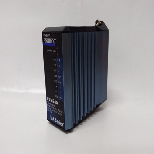
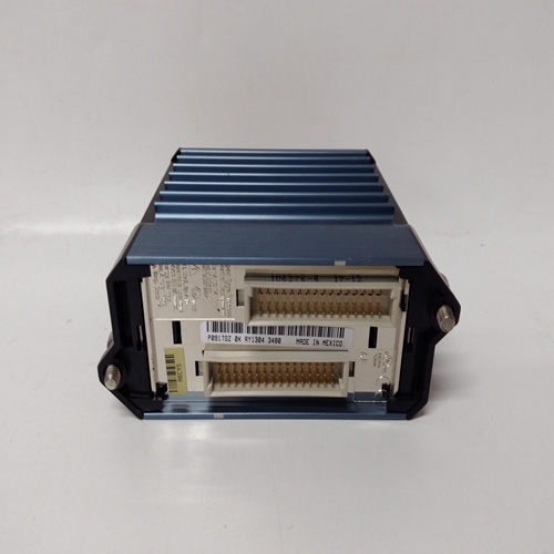

FBM240冗余8通道模块
通电-在热启动或热启动期间,当PU最后设置为“是”时,块将初始化为输入/输出状态和断电瞬间有效的运行时间。冷启动,PU最后设置为否,将输入/输出状态和运行时间初始化为0。E/I功能块可用于每个循环一个
选择模拟信号的基础,连接到输入E(外部)或输入I(内部),作为环路控制器。
E/I开关的位置可以在每个开关上改变输入ST和的正转换通常为连接至按钮块的PS输出PB2SW,配置用于瞬时动作。SE输出通常连接到的MD输入按钮块PB2SW。E/I开关位置将为:
操作员面板上由发光的LED显示:绿色代表E,红色代表I。
E/I开关位置也可以通过以下方式改变:通过Modbus或LIL网络的命令。
当PU LAST设置为YES时,E/I开关将在热天气或暖天气期间,在最后一个位置通电
开始在冷启动期间,它将在通电参数设置的位置。如果最后一个PU设置为“否”,E/I开关将在最后一个中通电热启动期间的位置,但在热启动或冷启动期间,
将在通电设置的位置通电参数IO(内部超驰)输入启用HI(1)输入
以临时选择内部输入作为功能块输出O1。该输入不影响E/I开关的位置。输出SE和SI指示E/I开关的实际位置。SE在E位置时为高(1),在低(0)时为低当处于I位置时。SI在I位置时为HI,在E位置时为LO。输出IS和ES指示:块输出的实际源。当O1为内部输入时,IS为高,当O1是外部输入时,为低输入当O1是外部输入时,ES为高电平,当O1为内部输入时ES为低电平。固件1.30及更高版本中的ESL功能块可以是在每个循环一次的基础上用于记录循环内的事件。
每个ESL输入可以分配一个用户标记(最多8个ASCII字符),当查看记录的
来自前面板的事件。事件,一旦由正向转换0>1输入,将保留在记录仪中直到复位。可通过设置输入R启动复位高(此输入对边缘敏感,将重置事件在前缘)或通过输入配置和将参数重置设置为“是”。
POWER UP - During a warm or a hot start, with PU LAST set to YES, the block will initialize with the
input/output states and elapsed time in effect at the instant power down occurred. A cold start, with PU LAST set to
NO, will initialize the input/output states and elapsed time to 0. E/I function blocks can be used on a one per loop
basis to select an analog signal, connected to input E
(External) or input I (Internal), as a setpoint for the
loop controller.
The position of the E/I switch can be changed on each
positive transition of input ST and will normally be
connected to the PS output of pushbutton block
PB2SW, configured for momentary action. The SE
output will normally be connected to the MD input of
pushbutton block PB2SW. E/I switch position will be
shown on the operator faceplate by a lighted LED:
green for E, red for I.
The E/I switch position can also be changed by
command over the Modbus or LIL network.
When PU LAST is set to YES, the E/I switch will
power up in the last position during a hot or a warm
start. During a cold start, it will power up in the
position set by the POWER UP parameter. If PU LAST is set to NO, the E/I switch will power up in the last
position during a hot start, but during a warm or cold start will power up in the position set by the POWER UP
parameter.
The IO (Internal Override) input enables a HI (1) input to temporarily select the Internal Input as the function block
output O1. This input does not affect the position of the E/I switch.
Outputs SE and SI indicate the actual position of the E/I switch. SE is HI (1) when in the E position and LO (0)
when in the I position. SI is HI when in the I position and LO when in the E position. Outputs IS and ES indicate
the actual source of the block output. IS is HI when O1 is the Internal input and is LO when O1 is the External
input. ES is HI when O1 is the External input and is LO when O1 is the Internal input.ESL function blocks, in firmware 1.30 and higher, can be
used on a one per loop basis to log events within the loop.
Each ESL input can be assigned a user tag (up to 8 ASCII
characters) that will be displayed when viewing the logged
events from the front panel. Events, once triggered by a
positive transition 0>1 input, will remain in the logger
until reset. Reset can be initiated either by setting input R
high (this input is edge sensitive and will reset the events
on the leading edge) or by entering configuration and
setting the parameter RESET to YES.

