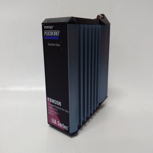
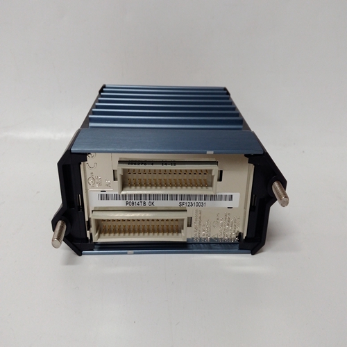
P0914TB通道隔离模块
DWE_功能块在以下情况下可用:安装了可选的以太网通信板11
在控制器中。它使控制器能够写入:通过以太网将数字数据传输到其他站点网络
最多可提供32个DWE_块。积木是按顺序分配,控制器范围,每次使用。
数字数据是打包成16位字的开/关数据。
IP地址参数用于配置IP目标Modbus设备的地址。MBADRES参数允许Modbus地址为:配置。当连接到其他西门子时摩尔控制器Modbus地址设置为1。
在某些情况下,其他Modbus设备可能使用不同地址或通过Modbus时TCP/IP网关:Modbus网络可能具有:多个设备,每个设备具有唯一地址。这个MB REG参数标识在Modbus设备中注册。
可以有三个写入更新选项:由UD类型参数配置。
1.一次将一次写入起始CL(Modbus起动线圈。控制器将在以下情况下写入:块输入值改变状态。
2.P2P将以以太网块中设置的控制器对等速率进行更新。
3.Ct将在控制器的循环时间更新。
Ct选项通常仅在写入时间关键更改时使用。输入T可用于触发写入。这
如果选择了oncE选项,输入值不变,并且可能存在担心接收设备丢失了值。
输出QS表示写入操作的质量,当写入未完成时,输出QS将变高(1)
成功地这通常与由于以下原因导致目标设备无法接收数据相关:通信故障或设备配置错误。
DYT_功能块执行ON或OFF由类型配置确定的输出延迟参数接通延迟-当输入P为低(0)时,输出O1为低。
如果P变高(1),则经过计时器启动并设置为O1达到DLY时间时为高,前提是P仍然为高的
关闭延迟-当输入P为高(1)时,输出为高的如果P变低(0),则已用定时器启动并设置O1在达到DLY时间时为低,前提是P为仍然很低。
在固件1.30及更高版本中,DLY时间为在整个显示范围内可调,范围为0.00000到9999999。在早期版本中,最短时间设置为0.1。如果延迟时间设置为小于站点的扫描时间,则延迟时间将等于扫描时间。
输出ET(经过的时间)将从0.0变为DLY时间值,并保持在该值,直到P重置输出。
输出RT(剩余时间)等于DLY时间-ET。
DWE_ function blocks are available when the
optional Ethernet communication board11 is installed
in the controller. It enables the controller to write
Digital data to other stations over the Ethernet
network.
Up to 32 DWE_ blocks are available. Blocks are
assigned in sequence, controller wide, with each use.
Digital data is On/Off data packed into a 16-bit word.
The IP ADRES parameter is used to configure the IP
address of the destination Modbus device. The MB
ADRES parameter allows a Modbus address to be
configured. When connecting to other Siemens
MOORE controllers the Modbus address is set to 1.
In some cases, other Modbus devices may use a
different address or when going through a Modbus
TCP/IP gateway a Modbus network may have
multiple devices, each having a unique address. The
MB REG parameter identifies the location of the
register in the Modbus device.
There are three write update options that can be
configured by the UD TYPE parameter.
1. oncE will write once to the START CL (Modbus
Starting Coil. The controller will write when any
block input value changes state.
2. P2P will update at the controller peer to peer rate set in the ETHERNET block.
3. Ct will update at the cycle time of the controller.
The Ct option is normally only used when writing time critical changes. Input T can be used to trigger a write. This
would be used in cases where the oncE option has been selected, input values do not change, and there may be a
concern that the receiving device has lost the values.
Output QS indicates the quality of the write operation and will go high (1) when the write is not completed
successfully. This is normally associated with failure of the destination device to receive data due to a
communication failure or a misconfiguration of the device.
DYT_ function blocks perform either an ON or OFF
output delay as determined by the TYPE configuration
parameter.
ON Delay - When input P is low (0), output O1 is low.
If P goes high (1), the elapsed timer starts and sets O1
high upon reaching the DLY TIME, provided P is still
high.
OFF Delay - When input P is high (1) the output is
high. If P goes low (0), the elapsed timer starts and sets
O1 low upon reaching the DLY TIME, provided P is
still low.
In firmware 1.30 and higher, the DLY TIME is
adjustable over the full range of the display, which is 0.00000 to 999999. In earlier versions, the minimum time
setting is 0.1. If the delay time is set to less than the scan time of the station, the delay time will equal the scan time.
Output ET (elapsed time) will ramp from 0.0 to the value of DLY TIME and remain there until P resets the output.
Output RT (remaining time) equals DLY TIME - ET.


