


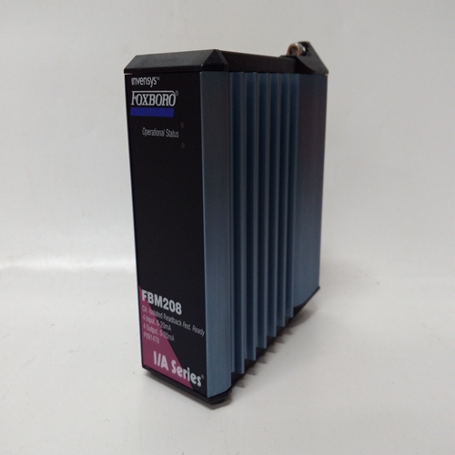
FBM208接口组件模块
固件1.30及更高版本中的DOS_功能块,向上传输至从控制器块接收的16个开/关信号与LonWorks网络上的远程节点互连,作为单个16位字值。最多可以有6个DOS块已使用,不超过Lon网络或控制器的内存限制。区块的每次使用将:分配了唯一的全站ID(如DOS01)。传输值的类型为SNVT_state,可以绑定到网络
远程节点中的变量,可以接收以下网络变量:
这种类型。这些区块将在LonWorks时可用
选项板安装在352P、353或354N控制器中。
每个功能块输入具有与其关联的模式。这个模式可以是正常模式或强制模式。使用电脑时
能够发送LIL或Modbus命令,模式可以是已更改,强制状态可以指定为高(1)或低(0)
价值通过网络可访问的值是两个交换机:
输入(N和F)和SPDT开关的位置,如所示
框图。“0”模式为正常模式,“1”为强制模式。功能块还具有与其相关联的质量状态。
当块确定丢失时,该状态将变为高(1)与绑定到该输入的Lon节点的输出通信。DOUT_功能块用于打开远程由外部电源供电的设备。反面外部电源的端子必须连接到这个车站很普通。晶体管开关将在以下情况下导通:块输入S为高(1),低时将关闭(0). 上有两个数字输出功能块
控制器板。DTM_功能块提供移位寄存器以保持模拟输入信号A持续一段时间,并将其从寄存器对寄存器,以在参数死区时间中配置的输入和输出。
输入AT可用于将死区时间调整为外部信号。用作块的实际移位寄存器
输出将等于输入的整个值(例如0.184=寄存器0、1.897=寄存器1)。
输出MA将提供寄存器0的移动平均值
输出寄存器除以寄存器数量
[例如,输出寄存器=50,MA=(R0+R1+R2+…+R50)/51]。
输入E断言高(1)将启用DTM块的操作。未配置此输入时,将设置高。低(0)输入将导致所有寄存器和输出等于输入A。
通电-在热启动或冷启动期间,所有输出将初始化为0,所有寄存器将初始化为第一次扫描时输入的值。
DOS_ function blocks, in firmware 1.30 and higher, transmit up
to 16 on/off signals received from a controller block
interconnection to a remote node on the LonWorks network as a
single 16-bit word value. A maximum of 6 DOS blocks can be
used, up to the limit of nodes allowed on the Lon network or the
memory limit of the controller. Each use of the block will be
assigned a unique station wide ID (e.g. DOS01). The transmitted
value is of type SNVT_state and can be bound to a network
variable in a remote node that can receive a network variable of
this type. These blocks will be available when the LonWorks
option board is installed in a 352P, 353, or 354N controller.
Each function block input has a mode associated with it. The
mode can be either NORMAL or FORCED. When using a PC
capable of sending LIL or Modbus commands, the mode can be
changed and the forced state can be assigned a high (1) or low (0)
value. The values accessible over the network are the two switch
inputs (N and F) and the position of the SPDT switch illustrated in
the block diagram. A mode of ‘0’ is Normal and ‘1’ is Forced.
The function block also has a quality status associated with it.
This status will go high (1) when the block determines it has lost
output communication with the Lon node bound to that input. DOUT_ function blocks are used to turn on remote
devices powered from an external source. The negative
terminal of the external power source must be connected to
station common. The transistor switch will turn on when
the block input S is high (1) and will turn off when low
(0). Two digital output function blocks are available on the
Controller Board.DTM_ function blocks provide shift registers to hold the
analog input signal A for a period of time and shift it from
register to register to provide an overall delay between
input and output as configured in parameter DEADTIME.
Input AT can be used to adapt the DEADTIME to an
external signal. The actual shift register used as the block
output will equal the whole value of input AT (e.g. 0.184 =
register 0, 1.897 = register 1).
Output MA will provide the moving average of register 0
to the output register divided by the number of registers
[e.g. output register = 50, MA = (R0+R1+R2+......+R50)/51].
Input E asserted high (1) will enable the operation of the DTM block. When this input is not configured, it will be
set high. A low (0) input will cause all registers and the outputs to equal the input A.
POWER UP - During a warm or cold start, all outputs will be initialized at 0 and all registers will be initialized to
the value of the input on the first scan.

