


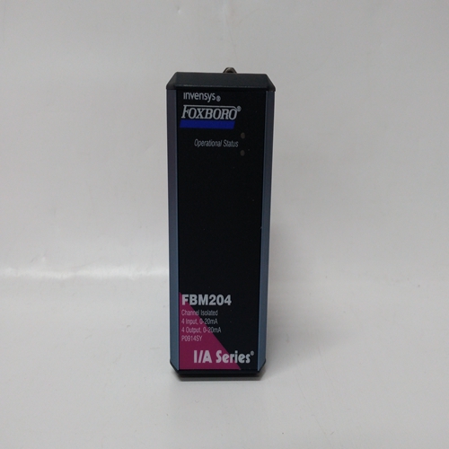
P0914SY电流输入模块
I/O扩展器板上有两个DINU_块。
这些块及其终端的固定名称(ID)第8.4节列出了名称。
输出CT表示缩放的(实际计数x K)总数:
上次复位后出现的输入脉冲。此输出是实数,并可用于多种应用,例如直接计数输入到BAT批次累加器
函数块或数学运算中,例如计算比率微调电路中计数之间的差异。
Output IS是输入的当前状态
块在每个控制器扫描周期开始时执行。它输入为低时将为低(0),输入为高时将为高(1)输入高。
输出SF是一个缩放频率(使用FREQ MIN和MAX参数),可以表示流速、速度或
具有频率信号的其他发射机变量
当FREQ MAX参数设置为25或更小时,20使用msec接触去抖动。
当使用触点去抖动时,脉冲输入必须保持开启20毫秒才能
被识别为有效脉冲。输出SF与频率呈线性关系,可使用CHR函数进行表征
如有必要,请阻止。使用MINSCALE、MAXSCALE和MAXSCAL将工程范围和单位分配给该信号,
DPP和ENGUNITS参数。它们可用于使用OR输出连接的其他块。
输入R将输出CT重置为0.0。输入D控制计数方向。当方向输入D为低(0)时
计数将向后移动,包括负值。方向输入功能允许使用倒计时
计数器,它允许复制以前的计算机脉冲接口执行的功能
脉冲/方向格式。输入TC断言高电平(1)将强制缩放计数跟踪外部信号。这可以用于CT输出用于设置值(例如设定点)的应用,该值可从另一个来源。
质量状态输出QS指示块输出的质量高(1)
当输出CT、IS或SF为坏时质量质量差表示在硬件转换电路。
通电-在PU最后设置为“是”的情况下CT输出将在最后一个值上电在热启动或热启动期间。如果设置为否,在热启动或冷启动期间,它将设置为0.0。在热启动、热启动或冷启动期间,数字滤波器将被临时旁路。
Two DINU_ blocks are available on the I/O expander board.
The fixed names (IDs) of these blocks and their terminal
designations are listed in Section 8.4.
Output CT represents the scaled (actual count x K) total of
input pulses that occurred since the last reset. This output is a
real number and can be used in a number of applications,
such as a direct count input to the BAT batch totalizer
function block or in math operations, such as computing the
difference between counts in a ratio trim circuit.
Output IS is the current state of the input at the time the
block is executed at the start of each controller scan cycle. It
will be low (0) when the input is low and high (1) when the
input is high.
Output SF is a scaled frequency (using the FREQ MIN and MAX parameters) that can represent flow rate, speed, or
other transmitter variable that has a frequency signal. When the FREQ MAX parameter is set to 25 or less, a 20
msec contact debounce is used. When contact debounce is used, a pulse input must remain on for 20 msec to be
recognized as a valid pulse. Output SF is linear with frequency and can be characterized using the CHR function
block if necessary. An engineering range and units are assigned to this signal using the MINSCALE, MAXSCALE,
DPP, and ENGUNITS parameters. They are available to other blocks using the OR output connection.
Input R resets output CT to 0.0. Input D controls the direction of the count. When direction input D is low (0), the
count will move backwards, including negative values. The direction input feature enables the use of count down
counters and it allows duplication of functions performed by previous computer pulse interfaces having a
Pulse/Direction format. Input TC asserted high (1) will force the scaled count to track an external signal. This can
be used in applications where the CT output is being used to set a value (e.g. setpoint) that can be changed from
another source.
The quality status output QS indicates the
quality of the block outputs and is high (1)
when outputs CT, IS, or SF are of bad
quality. Bad quality indicates a failure in the
hardware conversion circuit.
POWER UP - With PU LAST set to YES, the
CT output will power up at the last value
during a hot or warm start. If set to NO,
during a warm or a cold start, it will be set to
0.0. The digital filter will be temporarily bypassed during a hot, a warm or a cold start.

