


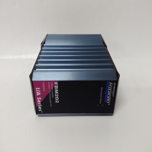

P0926EQ热电阻模块
DAM_功能块计算输入A和B,放大差分信号,并将与内部偏置和外部信号在输入C。未使用的输入设置为0.0。DID_功能块转换从LonWorks网络上的单个或多个节点分成16个块输出,供内的其他功能块使用控制器。最多可使用6个DID块,最多可使用Lon网络或内存上允许的节点数限制控制器的限制。块的每次使用将分配一个唯一的全站ID(如DID02)。输入连接为:通过“绑定”类型的每个输出变量建立远程节点设备中的SNVT_lev_disc(SNVT#22)用于DID功能块中的每个网络变量。这些当LonWorks选项板为:安装在352P、353或354N控制器中。0 NV NUM参数启用工作站的编号
已分配给输入0。所有后续网络变量为连续分配的。
每个功能块输出具有与其相关的模式。
这个模式可以是正常模式或强制模式。当使用能够发送LIL或Modbus命令的PC,模式可以更改,强制状态可以指定为高(1)或低(0)值。可通过网络访问的值包括:两个开关输入(N和F)和SPDT的位置方框图中所示的开关。“0”的模式为正常,强制执行“1”。每个功能块输出还具有相关的质量状态用它。当阻塞时,该状态将变为高(1)确定其已与Lon节点失去通信。如果任何单独的质量输出都是高质量的状态块输出也将为高。当可选以太网通信板10为:安装在控制器中。它启用控制器通过以太网。
最多可提供32个DIE_块。积木是按顺序分配,控制器范围,每个使用数字数据是封装为16位的开/关数据单词该数据被扇出至块输出D0–DF。IP地址参数用于配置源设备的IP地址。MB地址参数允许Modbus地址为:配置。当连接到其他西门子时摩尔控制器,Modbus地址设置为1。
在某些情况下,其他设备可能使用不同的地址或通过Modbus TCP/IP网关时,Modbus网络可能有多个设备,每个设备具有唯一的地址。
DAM_ function blocks compute the difference between
inputs A and B, amplify the difference signal, and sum the
resultant with an internal BIAS and an external signal at
input C. Unused inputs are set to 0.0.DID_ function blocks convert 16 on/off signals received from
a single or multiple nodes on the LonWorks network into 16
block outputs for use by other function blocks within the
controller. A maximum of 6 DID blocks can be used, up to the
limit of nodes allowed on the Lon network or the memory
limit of the controller. Each use of the block will be assigned a
unique station wide ID (e.g. DID02). Input connections are
established by ‘binding’ each output variable of type
SNVT_lev_disc (SNVT #22) in the remote node devices to
each network variable in the DID function block. These
blocks will be available when the LonWorks option board is
installed in a 352P, 353, or 354N controller.
The 0 NV NUM parameter enables the number that the station
has assigned to input 0. All subsequent network variables are
assigned consecutively.
Each function block output has a mode associated with it. The
mode can be either NORMAL or FORCED. When using a
PC capable of sending LIL or Modbus commands, the mode
can be changed and the forced state can be assigned a high (1)
or low (0) value. The values accessible over the network are
the two switch inputs (N and F) and the position of the SPDT
switch illustrated in the block diagram. A mode of ‘0’ is
Normal and ‘1’ is Forced.
Each function block output also has a quality status associated
with it. This status will go high (1) when the block
determines it has lost communication with the Lon node. If
any of the individual quality outputs are high the Quality
Status block output will also be high.
DIE_ function blocks are available when the
optional Ethernet communication board10 is
installed in the controller. It enables the controller
to read digital data from other stations over the
Ethernet network.
Up to 32 DIE_ blocks are available. Blocks are
assigned in sequence, controller wide, with each
use. Digital data is On/Off data packed into a 16-bit
word. This data is fanned out to block outputs D0 –
DF.
The IP ADRES parameter is used to configure the
IP address of the source device. The MB ADRES
parameter allows a Modbus address to be
configured. When connecting to other Siemens
MOORE controllers, the Modbus address is set to 1.
In some cases, other devices may use a different
address or when going through a Modbus TCP/IP gateway a Modbus network may have multiple devices, each
having a unique address.

