


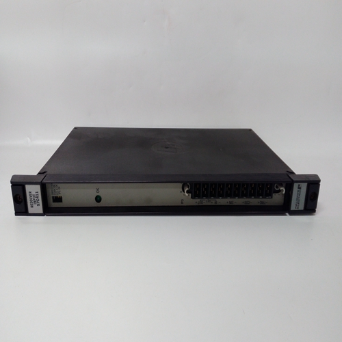
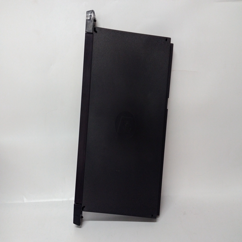
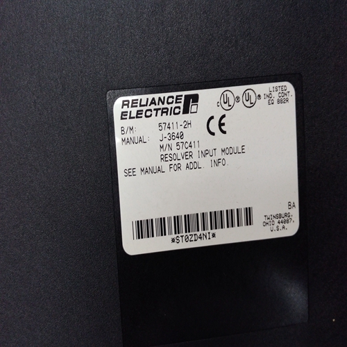
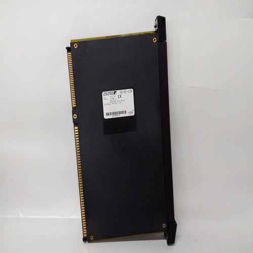
RELIANCE 57C411自动化模块
第六次按下工程卡报警按钮,然后测试将显示在消息显示屏上。最初,A1级别为:显示在数字显示器上,A1 LED点亮。注:测试功能自动禁止控制卡允许报警LED灯测试,防止意外报警
正在生成。为了测试继电器和故障LED,禁止按钮必须用于将控制卡设置为:不受约束的状态。
(12) 使用和按钮升高或降低模拟气体包括A1、A2、A3和欠量程在内的一系列级别上的级别故障值。检查所选控制卡是否指示模拟和数字显示器上的模拟气体液位,以及LED上指示适当的报警状态。
(13) 第七次按下工程卡报警按钮消息上将显示与STEL交替的测试
显示和关闭将显示在数字显示器上。
(14) 如果启用,使用和按钮切换STEL报警在OFF和ON之间。
(15) 第八次按下工程卡报警按钮,消息上将显示与LTEL交替的测试
和关闭将显示在数字显示器上。
(16) 如果启用,使用和按钮切换LTEL报警在OFF和ON之间。
(17) 进一步按下报警按钮将在警报级别再次。即A1、A2、A3、STEL、LTEL、TESTA1、A2和A3、TESTEL,TESTLTEL。
注:1.在测试过程中,可能会取消选定的控制卡通过按下所选控制卡前面板重置来选择模式/选择按钮。模拟气体液位和继电器将保持设置,允许多个控制卡同时测试。
重新选择控制卡时卡将返回测试模式。
2.如果取消禁止,外部继电器将运行。重要的使用测试模式时,始终确保信道控制
测试后,卡返回到未禁止状态。催化传感器桥电流调整
与胎圈mA按钮相关的操作仅适用当选择了配置用于催化的控制卡时
输入使用其他类型的控制卡按下按钮所选内容无效,并为此显示警告。
要进入催化传感器桥电流操作,请按以下步骤进行:
(1) 将工程钥匙插入工程卡前面板插座并检查解锁的LED()是否点亮。
(2) 按住所需的控制卡复位/选择按钮约1.5秒,并检查所选控制卡通过显示select(选择)来表示已选择偶像(3) 按下工程卡珠子mA按钮,然后检查所选控制卡信息是否显示显示mA,数字显示器显示实际电桥
Push the Engineering Card ALARMS push-button for a sixth time and
TEST will be displayed on the message display. Initially the A1 level is
displayed on digital display and the A1 LED is illuminated.
Note: The TEST function automatically inhibits the control card to allow
a lamp test of the alarm LEDs and prevent accidental alarms
being generated. In order to test the relays and the FAULT LED,
the INHIBIT push-button must be used to set the control card into
the uninhibited state.
(12) Use the and push-buttons to raise or lower the simulated gas
level over a range of levels that includes the A1, A2, A3 and underrange
fault values. Check that the selected control card indicates the
simulated gas level on the analogue and digital display, and that the
appropriate alarm states are indicated on the LEDs.
(13) Push the Engineering Card ALARMS push-button for a seventh time
and TEST alternating with STEL will be displayed on the message
display and OFF will be displayed on digital display.
(14) If enabled, use the and push-buttons to switch the STEL alarm
between OFF and ON.
(15) Push the Engineering Card ALARMS push-button for a eighth time,
and TEST alternating with LTEL will be displayed on the message
display and OFF will be displayed on digital display.
(16) If enabled, use the and push-buttons to switch the LTEL alarm
between OFF and ON.
(17) Further pushes of the ALARMS push-button will scroll through the
alarm levels again. ie. A1, A2, A3, STEL, LTEL, TESTA1, A2, A3, TESTSTEL,
TESTLTEL.
Note: 1. A selected control card may be deselected while in the TEST
mode by pushing the selected control card front panel RESET/
SELECT push-button. The simulated gas level and relay
states will remain set allowing several control cards to be
tested simultaneously. When the control card is reselected
the card will return to the TEST mode.
2. If the inhibit is removed, the external relays will operate.
IMPORTANT
When the TEST mode is used, always ensure that the channel control
card is returned to the uninhibited state after the test.CATALYTIC SENSOR BRIDGE CURRENT
ADJUSTMENT
The operation associated with the BEAD mA push-button only applies
when a control card has been selected that is configured for a catalytic
input. The pressing of the push-button with other types of control cards
selected has no effect and a warning is displayed to this effect.
To enter the catalytic sensor bridge current operation, proceed as follows:
(1) Plug the Engineering Key into the Engineering Card front panel
socket and check that the Unlocked LED ( ) is illuminated.
(2) Push and hold the required control card RESET/SELECT pushbutton for approximately 1.5 seconds and check that the selected
control card indicates it has been selected by displaying the select
icon.
(3) Push the Engineering Card BEAD mA push-button and
check that the selected control card message display
shows mA and the digital display shows the actual bridge
current.

