


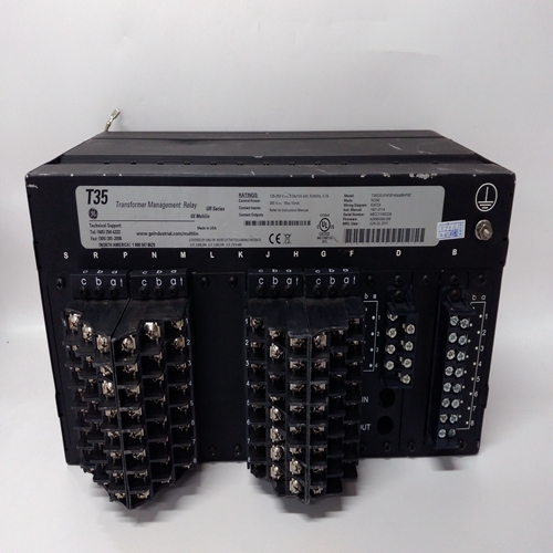
T35E00VFHF8FH6AM8HP6E通用电气模块
直流输出端
直流输出电缆连接的颜色编码为红色-+24V和黑色-0V。这些应连接到适当的直流输入卡终端。
建议将交流至直流电源装置连接使用装置后部提供的接地螺柱连接至系统接地。
为了额外的电气安全,剩余电流装置(RCD)类型:电源处应使用断路器。
将交流电源升级为直流电源单位
警告AC至DC电源单元内存在高电压。断开交流电源至少五分钟取下顶盖并执行任何操作前的分钟维护或升级操作。18.1总则有两种类型的交流到直流电源装置,一种是8路50W和16路50W。8路装置可升级为100W,并配备增加第二个50W开关模式模块。16路单元可升级至100W、150W或200W,增加50W开关模式模块,如有必要,配备50W子单元。
18.2 8路和16路交直流电源装置升级至100W
要将8路或16路交流至直流电源单元升级为:100W按如下步骤进行:
(1) 卸下并固定电源顶盖的螺钉供应装置,然后提起盖子。
(2) 切断并拆下固定未使用空调的固定带,以及至子单元机箱的直流连接电缆。
(3) 在要添加到50W子单元的50W开关模式模块上,从下侧拆下并丢弃四个填料螺钉但是,保留模块的长螺母和垫圈。
(4) 在要添加到50W子单元的50W开关模式模块上,确保印刷电路板下的垫片:正确定位。(5) 插入模块,方向与已安装的方向相同模块,进入50W子单元内的空位置,以及
使用步骤(3)中保留的垫圈和长螺母固定。
(6) 连接50W子单元第二交流输入和24V直流输出连接交流输入端子CN1和直流输出的电缆接头
终端CN2分别处于新增的50W切换模式
模块如下所示:
(7) 重新安装顶盖。
18.3 16路交流至直流电源装置升级至150W或200W
DC Output
The dc output cable connections are colour coded RED - +24V and
BLACK - 0V. These should be connected to the appropriate DC
Input Card terminals.
It is recommended that the AC to DC Power Supply Unit is connected
to the system earth using the earth stud provided at the rear of the unit.
For additional electrical safety a Residual Current Device (RCD) type
circuit breaker should be used at the supply source.
UPGRADING THE AC TO DC POWER SUPPLY
UNITS
WARNING
High voltages exist within the AC to DC Power Supply Unit.
Disconnect from the ac supply for a period of at least five
minutes before removing the top cover and carrying out any
maintenance or upgrade operation.
18.1 General
There are two types of AC to DC Power Supply Unit, an 8-Way 50W
and 16-Way 50W. The 8-way unit may be upgraded to 100W with the
addition of a second 50W Switched Mode Module. The 16-way unit
may be upgraded to 100W, 150W or 200W with the addition of 50W
Switched Mode Module(s) and if necessary a 50W Sub Unit.
18.2 8-Way and 16-Way AC to DC Power Supply Unit Upgrade
to 100W
To upgrade the 8-Way or 16-Way AC to DC Power Supply Units to
100W proceed as follows:
(1) Remove and retain the screws securing the top cover of the power
supply unit and lift the cover clear.
(2) Cut and remove the retaining straps that secure the unused ac and
dc connecting cables to the sub-unit chassis.
(3) On the 50W Switched Mode Module to be added to the 50W SubUnit, remove and discard the four packing screws from the underside
of the module, however, retain the long nuts and washers.
(4) On the 50W Switched Mode Module to be added to the 50W SubUnit, ensure that the spacers under the printed circuit board are
correctly located.(5) Insert the module, with the same orientation as the already fitted
module, into the vacant position inside the 50W Sub Unit and
secure using the washers and long nuts retained in Step (3).
(6) Connect the 50W Sub Unit second ac input and 24V dc output
cable connectors to the ac input terminal CN1 and dc output
terminal CN2 respectively on the added 50W Switched Mode
Module as shown below:
(7) Refit the top cover.
18.3 16-Way AC to DC Power Supply Unit Upgrade to 150W or
200W

