


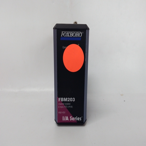
P0914SV输入输出卡件
4-20mA变送器
4-20mA变送器电缆的最大线路电阻由系统57供电,随电压和电流变化
变送器的要求。它还受到最低要求的限制系统57提供的电源电压。
最大线路回路电阻计算如下:虚拟现实
-VsRL=s
式中:RL=总线路电阻(欧姆)
Vr=系统57的最小直流电源(V)
Vs=传感器电压(V)
s=传感器电流(A)
使用Vr进行上述计算18V将容纳最坏的情况是低直流电源情况。
每个铁芯的最大电阻可通过上述公式计算得出:
配置如下
RL核心的最大电阻=欧姆控制卡传感器驱动模块配置
12.1概述安装在单通道控制卡上的传感器驱动模块具有影响传感器操作的配置链接。这个
以下各节确定了允许配置的链接:检查。
12.2单通道控制卡,催化输入链路设置
注意安全
传感器驱动模块的设置不正确,催化电流量程链接可能会对传感器造成永久性损坏。
催化式传感器驱动模块有三个焊点位置(LK1至LK3),其允许设置电桥电流范围。以下
范围可用:量程电流LK1、LK2、LK3
1 219mA至283mA S/C S/C
2 66mA至230mA S/C S/C O/C
3 118mA至182mA O/C S/C O/C
4 70mA至134mA O/C O/C
S/C-短路,O/C-断路
上述信息仅用于配置
传感器驱动模块,待检查催化。当前范围为:出厂设置,未参考
系统57技术手册。
12.3单通道控制卡,4-20mA输入链路设置
注意安全
传感器驱动模块设置不正确,4-20mA
配置链接可能会对控件造成永久性损坏
卡、传感器驱动模块或传感器。传感器驱动模块4-20mA配有13个跨接链路
(LK1至LK13),其允许容纳多种不同的传感器配置。通过安装所提供的跳线来闭合连杆,以便:
连杆的两个销连接。未使用的链接应具有
完全或小心地从传感器驱动模块上拆下跳线安装在未使用连杆的单个销上,如下所示:传感器驱动模块打开、关闭和备用链路安排
4-20mA Transmitters
The maximum line resistance of cabling for a 4 - 20mA transmitter
powered from the System 57 varies with the voltage and current
requirements of the transmitter. It is also subject to the minimum
supply voltage available from the System 57.
Maximum line loop resistance is calculated as follows:
Vr
- Vs
RL =
I
s
Where: RL = Total Line Resistance (ohms)
Vr = Minimum DC Supply to System 57 (V)
Vs = Sensor Voltage (V)
I
s = Sensor Current (A)
Making the above calculation using a Vr
of 18V will accommodate the
worst case low dc supply situation.
The maximum resistance per core can be calculated from the above
configurations as follows:
RL
Maximum Resistance of Core = ohms CONTROL CARD SENSOR DRIVE MODULE
CONFIGURATION
12.1 General
The sensor drive modules fitted to the Single Channel Control Cards
have configuration links that effect the operation of the sensor. The
following sections identify the links to allow the configuration to be
inspected.
12.2 Single Channel Control Card, Catalytic Input Link Settings
CAUTION
Incorrect setting of the Sensor Drive Module, Catalytic current
range links may cause permanent damage to the sensor.
The Sensor Drive Module, Catalytic has three solder link positions (LK1
to LK3) which allow setting of the bridge current range. The following
ranges are available:
Range Current LK1 LK2 LK3
1 219mA to 283mA S/C S/C S/C
2 66mA to 230mA S/C S/C O/C
3 118mA to 182mA O/C S/C O/C
4 70mA to 134mA O/C O/C O/C
S/C - Short Circuit, O/C - Open Circuit
The above information is only provided to allow the configuration of the
Sensor Drive Module, Catalytic to be checked. The current range is
factory set and should not be altered without reference to the
SYSTEM 57 Technical Manual.
12.3 Single Channel Control Card, 4 - 20mA Input Link Settings
CAUTION
Incorrect setting of the Sensor Drive Module, 4 - 20mA
configuration links may cause permanent damage to the Control
Card, Sensor Drive Module or Sensor.
The Sensor Drive Module, 4 - 20mA is fitted with thirteen jumper links
(LK1 to LK13) which allow numerous different sensor configurations to be accommodated. A link is closed by fitting the jumper provided so that
the two pins of the link are connected. Unused links should have their
jumper removed from the Sensor Drive Module altogether or carefully
fitted over a single pin of an unused link as follows:
Sensor Drive Module Open, Closed and Spare Link
Arrangements

