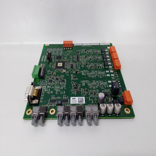
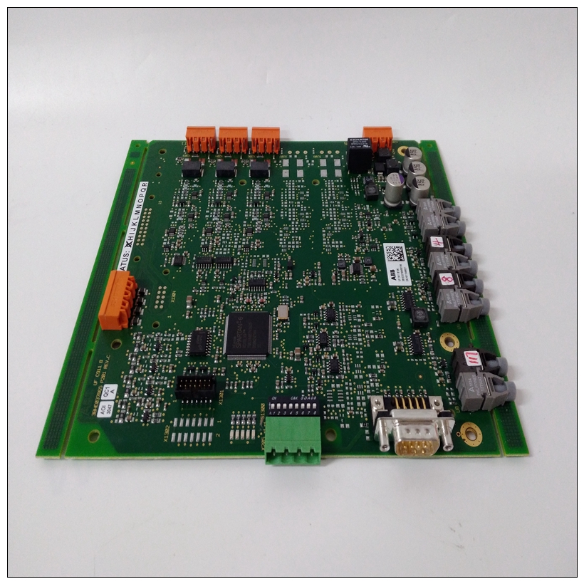
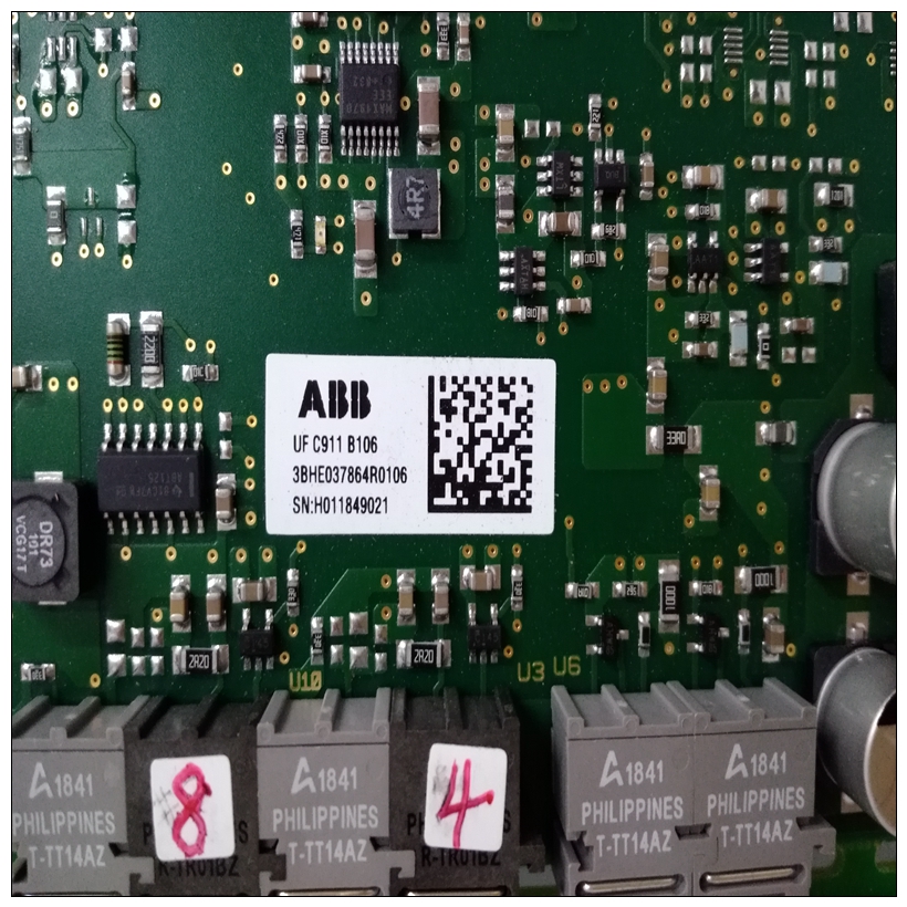
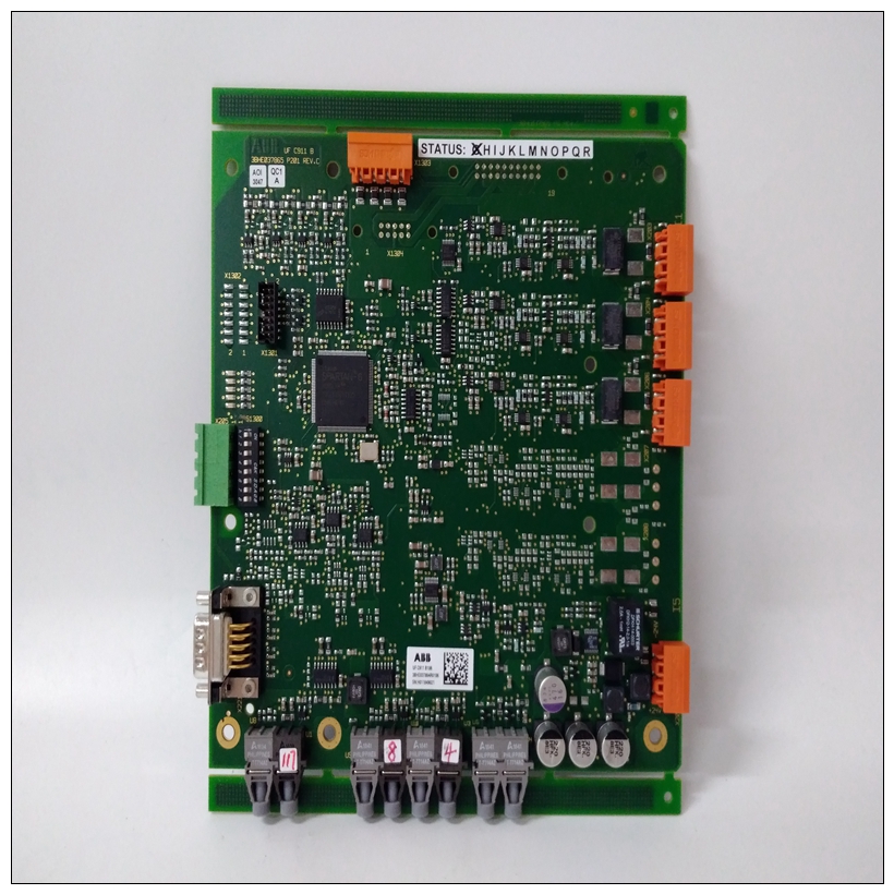
3BHE037865P201高压板卡
提取槽
提取工具与下方的提取槽配合使用选择按钮,将卡从机架中取出。提取该工具作为随附钥匙套件(05701-A-0550)的一部分提供机架组件。
通过首先拧下两个卡固定螺钉来移除卡,一个在卡片的顶部,另一个在卡的底部,然后将提取工具钩入提取槽,然后轻轻拉动从机架中取出卡片。
2.6展示、标签和封面
透明有机玻璃盖夹在前面板上,并保留标签,标签:提供控制卡类型、传感器刻度、LED和按钮功能。
使用两种不同的标签颜色:a、 灰色/蓝色-装有催化传感器驱动的控制卡模块。
b、 紫色-控制卡,配备4-20mA传感器驱动模块。
首先将有机玻璃盖拆下从机架中卸下控制卡然后在前面板的内部,就在液晶显示器。钝物钝物,如然后将螺丝刀推过用于松开有机玻璃盖的孔。
有机玻璃盖上的小凹槽允许插入标签以指示:通道标签名称或气体类型。工程卡
3.1概述
工程卡提供设施,以允许每个控制卡:询问并允许正常维护功能,如:进行校准。它还充当允许配置每个卡的工程接口。3.2 LED指示灯前面板顶部的两个指示灯
工程卡:显示以下设备的运行状态:
卡片:3.2.1-绿色LED
持续点亮的LED指示灯指示
正确的直流电源通过直流连接到机架输入卡。
以大约两秒的间隔闪烁LED,指示低直流电源输入电平。
以大约0.5秒的间隔闪烁LED,表示硬件故障。
Extraction Slot
An extraction tool is used in conjunction with the extraction slot, just below
the select push-button, to remove the card from the rack. The extraction
tool is provided as part of the Key Kit (05701-A-0550) supplied with each
rack assembly.
The card is removed by first unscrewing the two card securing screws,
one at the top of the card and the other at the bottom of the card, and then
hooking the extraction tool into the extraction slot and then gently pulling
the card out of the rack.
2.6 Display Label and Cover
A clear perspex cover clips to the front panel and retains the label which
provides identification of the control card type, sensor scale, LED and
push-button functions.
Two different label colours are used:
a. Grey/Blue - Control cards fitted with Catalytic Sensor Drive
Modules.
b. Violet - Control cards fitted with 4 - 20mA Sensor Drive
Modules.
The perspex cover is removed by first
removing the control card from the rack
and then locating a small hole on the
inside of the front panel just above the
LCD display. A blunt object, such as a
screwdriver, is then pushed through the
hole to unclip the perspex cover.
A small recess in the perspex cover
allows a label to be inserted to indicate
the channel tag name or gas type.
ENGINEERING CARD
3.1 General
The Engineering Card provides facilities to allow each control card to be
interrogated and to allow normal maintenance functions such as
calibration to be carried out. It also acts as a connecting point for the
engineering interface which allows each card to be configured.
3.2 LED Indicators
Two indicators at the top of the front panel of the
Engineering Card indicate the operational status of
the card:
3.2.1 - Green LED
A continuously illuminated LED indicates that the
correct dc power is connected to the rack via the DC
Input Card.
A flashing LED at approximately two second intervals,
indicates a low dc power input level.
A flashing LED at approximately 0.5 second intervals,
indicates a hardware fault.


