


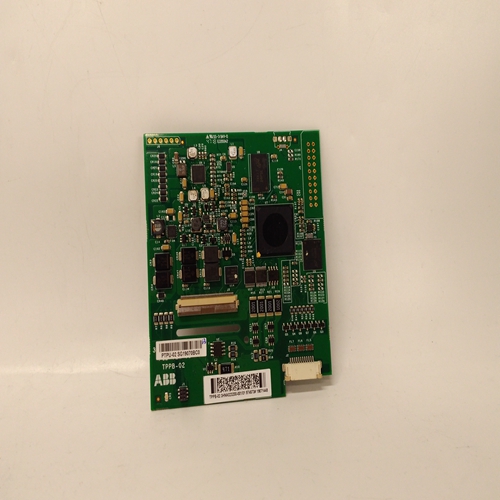
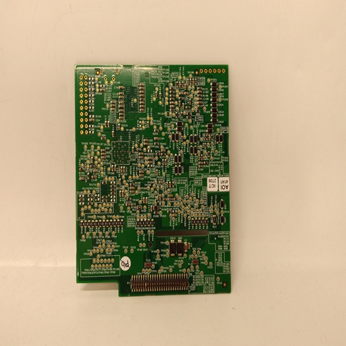
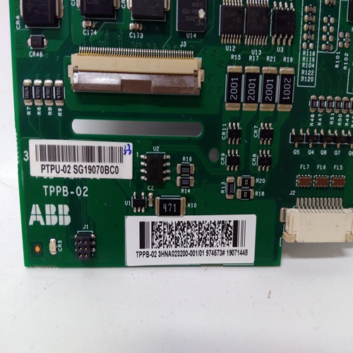
3HNA023200-00101处理器卡件
工程卡始终安装在机架的右侧插槽,提供:a、 24V直流输入与直流输入的布线板卡到机架的背板。
b、 背板串行通信控制器和监视器。
c、 时间和日期参考。
d、 RS232外部工程接口。
e、 根据安全级别,操作
以下机架设施:催化传感器头电流监测和调整
报警设定点检查、调整和测试。传感器信号零点调整。
传感器信号量程调整和设置
传感器寿命监测值。
传感器在线监测。
启用控制卡报警抑制。
检查和调整系统时钟。
工程卡上可安装四个可选模块之一:
a、 主报警更新模块
当在任何位置出现新警报时,该设施提供指示
机架中的通道,即使先前的报警条件已经存在存在。
b、 事件打印模块
该设施提供带有时间戳的报警和故障报告事件发生时,系统状态按预定规则间隔。
c、 Modbus接口模块RS422/485该设施提供以下设备之间的数字通信:系统57控制系统和外部计算机系统使用RS422/485串行数据格式和Modbus通信协议
d、 Modbus接口模块RS232
该设施提供以下设备之间的数字通信:
系统57控制系统和外部计算机系统使用
RS232串行数据格式和Modbus通信
协议机架的直流电源通常通过直流进入子机架
输入卡(零件号05701-A-0325)。可以提供该电源
由用户从外部标称24V直流电源供电。直流电源为:
通过工程卡和子架背面布线至所有
机架中的卡,并由直流输入卡上的保险丝保护。
有一个由两部分组成的接线板TB1,用于帮助拆卸板卡
而不断开每个连接的导线。
如果需要,也可以连接备用备用电池电源
至辅助直流输入连接。
PSU和AUX连接通过二极管相互隔离。
直流输入卡还提供RFI滤波和反极性保护
The Engineering Card is always fitted into the
right-hand slot of the rack and provides:
a. Routeing of the 24V dc input from the DC Input
Card to the backplane of the rack.
b. A backplane serial communications controller
and monitor.
c. A time and date reference.
d. An RS232 external engineering interface.
e. Depending upon the security level, the operation
of the following rack facilities:
Catalytic sensor head current monitoring and
adjustment.
Alarm set point checking, adjustment and
testing.
Sensor signal zero adjustment.
Sensor signal span adjustment and setting of
sensor life monitoring values.
Sensor line monitoring.
Enabling of control card alarm inhibit.
Checking and adjustment of the system clock.
One of four optional modules may be fitted to the Engineering Card:
a. Master Alarm Update Module
This facility provides an indication when a new alarm occurs on any
channel in the rack, even if a previous alarm condition already
exists.
b. Event Printing Module
This facility provides time stamped reporting of alarm and fault
events as they occur and system status at predetermined regular
intervals.
c. Modbus Interface Module RS422/485
This facility provides for digital communication between the
System 57 Control System and an external computer system using
the RS422/485 serial data format and the Modbus communication
protocol.
d. Modbus Interface Module RS232
This facility provides for digital communication between the
System 57 Control System and an external computer system using
the RS232 serial data format and the Modbus communication
protocol.The dc power to the rack normally enters the sub-rack via the DC
Input Card (Part Number 05701-A-0325). This power may be supplied
by the user from an external nominal 24V dc supply. The dc supply is
routed through the Engineering Card and sub-rack back plane to all
cards in the rack and is protected by a fuse on the DC Input Card.
There is a two part terminal block, TB1, to aid removal of the card
without disconnecting each of the connected wires.
If required, a stand-by backup battery supply may also be connected
to the auxiliary dc input connections.
The PSU and AUX connections are isolated from each other by diodes.
The DC Input Card also provides RFI filtering and reverse polarity
protection.

