


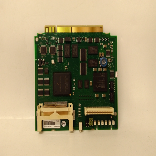
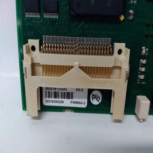
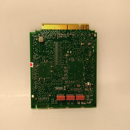
PM866A-2控制单元模块
在需要将现场接线连接到系统后部,机架中央分为前部和后部各部分由一块印刷电路板背板组成,提供公共单个信道控制卡之间的功率和信号路由。接口时,通道控制卡安装在机架前部/继电器卡直接安装在通道控制卡的后面机架后部。信道控制卡及其各自接口/继电器卡通过插头和插座互连安排在需要将现场接线连接到
系统前端、通道控制卡和接口/继电器卡一个接一个安装在6U机架中。底板印刷电路板仍然提供公共电源和信号短路时单个通道控制卡之间的路由卡后部的电缆将每个通道控制卡连接到:它们各自的接口/中继卡。
使用以下方法对系统进行简单的校准和检查:安装在每个机架上的工程卡上的按钮。更多可以使用以下之间的RS232链路执行复杂配置:工程卡和外部IBM兼容个人运行工程接口软件的计算机。工程卡可以通过以下方式提供其他功能:插入工程卡的可选模块。见下文:模块操作说明手册:05701M5006 Modbus接口模块
05701M5007事件打印模块
05701M5008主报警更新模块
5701控制系统如图1所示,概述如下:5701系列控制系统是基于微处理器的系统其显示连接的气体检测器的读数和状态。这个系统提供了复杂的报警处理设施,具有完整的维护能力。机架系统配有多个单通道控制卡
每个都有一个相关的现场/中继卡,提供必要的传感器输入和可选继电器输出连接。简单警报
每个通道控制卡提供处理和操作。
复杂的报警处理是通过通过机架背板的指定数量的控制卡。每个机架上都安装了一个工程卡,用于控制机架背板通信、控制卡询问和便于维护。此外,安装到工程卡可以提供额外的系统输出。系统电源、辅助电源和备用电池系统通常都通过直流输入卡连接到机架,但是,对于高完整性系统安装,电源可以是直接连接到每个单独的控制卡。
In a system where the field wiring is required to be connected to the
rear of the system, the rack is centrally divided into front and rear
sections by a printed circuit board backplane which provides common
power and signal routeing between individual Channel Control Cards.
Channel Control Cards are fitted at the front of the rack while Interface/
Relay cards are fitted directly behind the Channel Control Cards at the
rear of the rack. The Channel Control Cards and their respective
Interface/Relay Cards are interconnected by a plug and socket
arrangement.
In a system where the field wiring is required to be connected to the
front of a system, the Channel Control Cards and Interface/Relay
Cards are mounted one above the other in a 6U rack. The backplane
printed circuit board still provides the common power and signal
routeing between the individual Channel Control Cards while short
cables at the rear of the cards connect each Channel Control Card to
their respective Interface/Relay Card.
Simple calibration and checking of the system is carried out using
push buttons on the Engineering Card fitted to each rack. More
complex configuration can be carried out using the RS232 link between
the Engineering Card and an external IBM compatible personal
computer running the engineering interface software.
Additional functions can be provided by the Engineering Card using
optional modules that plug into the Engineering Card. See the following
module operating instruction manuals:
05701M5006 Modbus Interface Module
05701M5007 Event Printing Module
05701M5008 Master Alarm Update Module
The 5701 Control System is shown in Figure 1 with an overview at
Figure 2.
INTRODUCTION
The 5701 Series Control System is a microprocessor based system
which displays the reading and status of connected gas detectors. The
system provides complex alarm handling facilities with a full
maintenance capability.
A rack system is fitted with a number of single channel control cards
each with an associated field/ relay card which provides the necessary
sensor input and optional relay output connections. Simple alarm
handling and operation is provided by each channel control card.
Complex alarm handling is achieved by communication between a
specified number of control cards via the backplane of the rack.
An engineering card is fitted to each rack and provides control of the
rack backplane communications, control card interrogation and
facilitates maintenance. In addition, optional modules fitted to the
engineering card can provide additional system outputs.
System power supplies, auxiliary power supplies and battery back up
systems are all normally connected to the rack via a DC Input Card,
however, for high integrity system installations power supplies can be
connected directly to each individual control card.

