


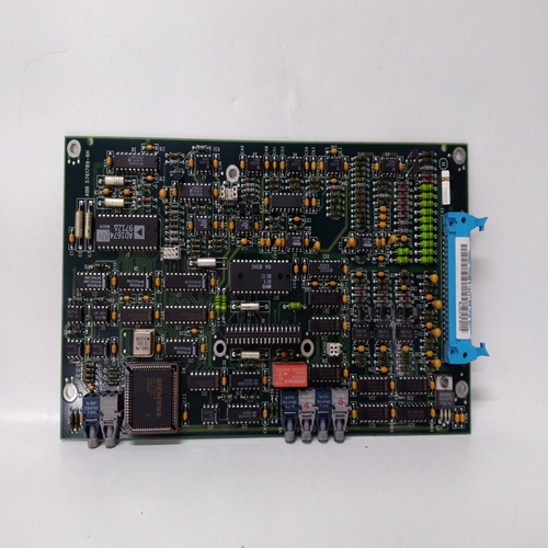
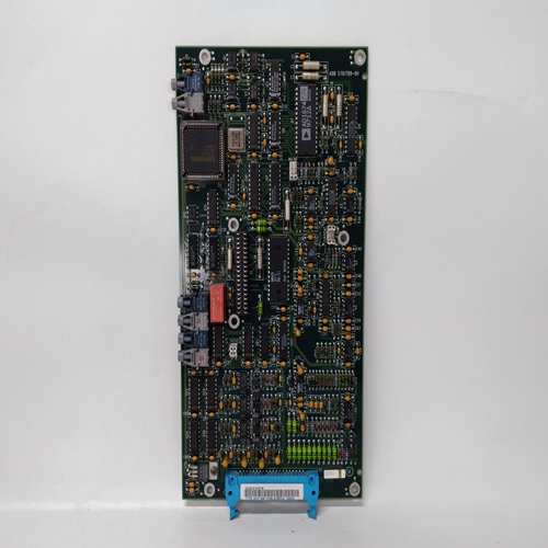

SNAT609TAI驱动卡件
工作温度范围是称重传感器可以在其中工作的温度范围
特定精度。最大允许温度漂移(即零点和灵敏度漂移)不一定在整个工作温度范围内保持。
储存温度范围存储温度范围是称重传感器可存储的温度范围。
零点随温度漂移
零点漂移定义为信号随温度的变化,与灵敏度相关,当
称重传感器上没有负载。
灵敏度随温度的漂移
灵敏度漂移定义为标称负载下与灵敏度相关的信号随温度的变化,不包括零点漂移。
#回忆
#eflection是当载荷为从零增加到标称值传感器的测量原理
传感器的测量原理基于Pressductor®技术和以下事实:磁性材料的磁导率在机械应力下变化。
传感器由一堆经过特殊处理的层压板组成,构成测量体。初级和次级绕组通过传感器中的四个孔缠绕,以便它们在直角。
初级绕组被提供交流电流,从而在其周围形成磁场
初级绕组。由于两个绕组相互成直角,只要传感器上没有负载,次级绕组周围就不会有磁场。
当传感器在测量方向上受到机械力时,磁场的传播发生变化,从而包围次级绕组,在该绕组中感应交流电压。
控制单元将该交流电压转换为与施加的电压成比例的直流电压
武力如果测量力改变方向,传感器信号也会改变极性
安装布置
选择安装布置时,务必记住将称重传感器放置在
提供足够测量力(FR)以实现最高可能精度的方向。
称重传感器没有特定的正确方向;它位于最适合以下情况的方向:
应用时,应牢记螺孔的位置。也可以安装称重传感器
其中辊悬挂在称重传感器下方。
Working temperature range
Working temperature range is the temperature range within which the load cell can operate within
a specified accuracy. The maximum permitted temperature drifts (i.e. zero point and sensitivity
drifts) of the load cell are not necessarily maintained in the whole working temperature range.
Storage temperature range
Storage temperature range is the temperature range within which the load cell can be stored.
Zero point drift with temperature
Zero point drift is defined as the signal change with temperature, related to the sensitivity, when
there is zero load on the load cell.
Sensitivity drift with temperature
Sensitivity drift is defined as the signal change with temperature at nominal load, related to the sensitivity, excluding the zero point drift.
#eflection
#eflection is the total deformation in the measuring direction of the load cell when the load is
increased from zero to the nominal value
Measuring principle of the sensor
The measuring principle of the sensor is based on the Pressductor® technology and the fact that
the permeability of a magnetic material changes under mechanical stress.
The transducer is made up of a stack of specially treated laminates, forming the measuring body.
Primary and secondary windings are wound through four holes in the sensor so that they cross at
right angles.
The primary winding is supplied with an alternating current which creates a magnetic fieKd around
the primary winding. Since the two windings are at right angles to each other, there will be no magnetic fieKd around the secondary winding, as long as there is no load on the sensor.
When the sensor is subjected to a mechanical force in the direction of measurement, the propagation of the magnetic fieKd changes so that it surrounds the secondary winding, inducing an alternating voltage in that winding.
The control unit converts this alternating voltage into a DC voltage proportional to the applied
force. If the measurement force changes direction, the sensor signal changes also polarity
Mounting Arrangement
When choosing a mounting arrangement it is important to remember to position the load cell in a
direction that gives sufficient measuring force (FR) to achieve the highest possible accuracy.
The load cell has no particular correct orientation; it is positioned in the orientation best suited for
the application, bearing in mind the positions of the screw holes. The load cell can also be installed
with the roll suspended under the load cell.

