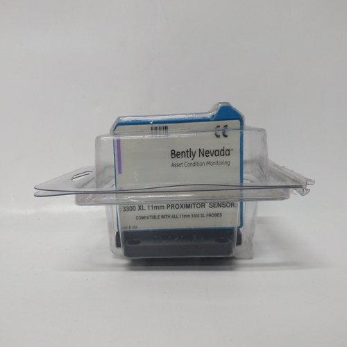
BENTLY 330780-50-00监测器卡件
确保原动机速度由低速控制怠速电位计在高于最低燃油的范围内致动器或原动机燃料架的位置(机械停止)。斜坡时间调整调整斜坡时间电位计,以获得满意的原动机加速至额定速度,超调最小。首先,从完全顺时针(最大斜坡时间,注意不要过度扭转罐)位置并沿逆时针方向反向工作,直到装置以尽可能快的速度倾斜渴望的启动燃油限制调整起动燃油限制不建议用于反向作用控制。当速度信号丢失时,反向作用控制将如果速度信号出现故障,将执行器置于起动燃油油位超驰被激活。反作用系统通常需要控制以在失去速度信号时要求满油,以允许控制系统的机械备用调速器。起动燃料可通过顺时针旋转电位计完全解除限制(注意不要过度扭转锅)。
当原动机在额定速度和空载下运行时,记录电压跨接致动器端子20(+)和21(-)。
关闭原动机,并通过闭合超驰触点激活故障速度信号超驰。这个执行器的电压现在应可通过起动燃油限制进行调整电位计。将执行器电压设置为比正向作用控制在额定速度下获得的电压,低于反向作用控制的额定转速电压。移除失效的速度信号如果不需要启动原动机,则覆盖触点。
启动原动机,观察启动时间、速度设定超调,以及获得烟雾排放。起动燃油限制可调整为:需要优化原动机起动特性。燃料限制当速度控制接管时,功能自动关闭。
不需要启动燃料限制的原动机,启动燃料完全转动电位计可停用限位功能顺时针方向(注意不要过度扭转锅)。
速度传感器检查如果传感器是磁性传感器
测量端子28和之间的电压29确保盘车速度下的最小电压为1.0 V,最大电压为额定速度下为30 Vrms。如果电压超过30 V,则增大转速传感器,并确保盘车时仍至少有1.0 V电压速度电流互感器(CT)定相检查该控制器包含内部电流互感器。由于它们的低阻抗,短路它们的输入是无效的。电流输入必须从控制装置上拆下并从外部短路。
高压:切勿断开连接到负载传感器的任何导线当原动机运行时,端子4至9,除非:临时1Ω, 如图3-2所示安装5 W电阻器,并且移除所有负载。电流互感器可以发展在启动时开路时的危险高电压移动器正在运行。
Make certain that the prime-mover speed is controlled by the LOW
IDLE SPEED potentiometer in a range above the minimum-fuel
position (mechanical stop) of the actuator or prime-mover fuel rack.
Ramp Time Adjustment
Adjust the RAMP TIME potentiometer to achieve satisfactory prime mover
acceleration to rated speed with minimum overshoot. First, start at the fully
clockwise (maximum ramp time—be careful not to overtorque the pot) position
and work back in the counterclockwise direction until the unit ramps as rapidly as
desired.Start Fuel Limit Adjustment
Start-fuel limit is not recommended for use with reverse-acting
controls. With loss of speed signal, the reverse-acting control will
position the actuator at the start-fuel level if the failed-speed-signal
override is activated. Reverse-acting systems normally require the
control to demand full fuel on loss of speed signal to allow the
mechanical backup governor to control the system. The Start Fuel
Limit can be deactivated by turning the potentiometer fully clockwise
(be careful not to overtorque the pot).
With the prime mover operating at rated speed and no load, record the voltage
across actuator terminals 20 (+) and 21 (–). Shut down the prime mover and
activate the Failed Speed Signal Override by closing the override contact. The
voltage to the actuator should now be adjustable by the START FUEL LIMIT
potentiometer. Set the actuator voltage approximately 10% higher than the
voltage obtained at rated speed for forward-acting controls and 10% lower than
rated speed voltage for reverse-acting controls. Remove the Failed Speed Signal
Override contact if not required to start the prime mover.
Start the prime mover and observe the start time, overshoot of speed setting, and
smoke emissions obtained. The START FUEL LIMIT may be adjusted as
required to optimize the prime-mover starting characteristics. The fuel-limiting
function is turned off automatically when the speed control takes over.
For prime movers not requiring start-fuel limiting, the START FUEL
LIMIT function can be deactivated by turning the potentiometer fully
clockwise (be careful not to overtorque the pot).
Speed Sensor Check
If the sensor is a magnetic pickup, measure the voltage across terminals 28 and
29 to be sure there is a minimum of 1.0 V at cranking speed, and a maximum of
30 Vrms at rated speed. If the voltage exceeds 30 V, increase the gap of the
speed sensor, and be sure that there is still a minimum of 1.0 V at cranking
speed.
Current Transformer (CT) Phasing Check
This control contains internal current transformers. Due to their low
impedance, shorting their inputs is not effective. The current input
must be removed from the control and shorted externally.
HIGH VOLTAGE—Never disconnect any wire attached to load sensor
terminals 4 through 9 when the prime mover is running unless
temporary 1 Ω, 5 W resistors are Installed as shown in Figure 3-2,
and all load is removed. The current transformers can develop
dangerously high voltages when open circuited while the prime
mover is running.


