


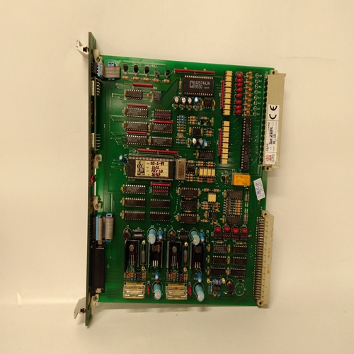
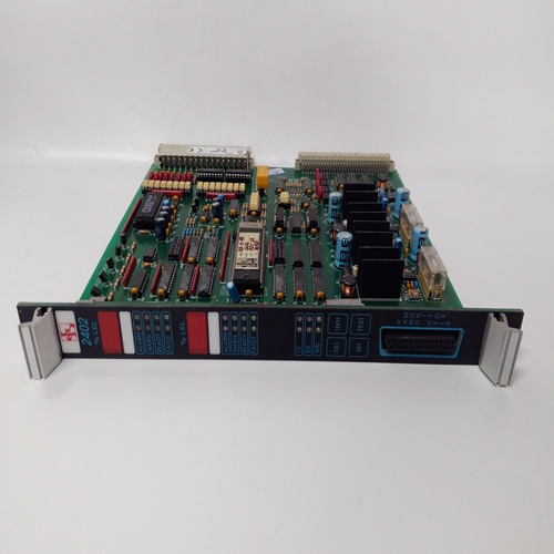
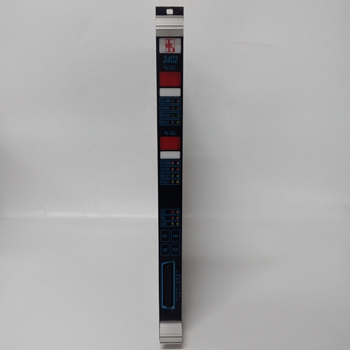
SES 2402 GAS2402温度卡件
初始预启动设置启动原动机前,请阅读整个程序。
额定转速电位计是该系统中唯一的多转电位计控制所有其他罐都是单圈的。小心不要转动这些锅已经停不住了。
额定转速
A、 将额定转速电位计设置为最小值(完全逆时针方向)。
B、 将外部速度微调(如果使用)设置到中间位置。
2.在中间位置复位设置。
3.增益设置在中间位置。
4.斜坡时间设置为最大值(完全顺时针方向,注意不要过度扭转锅)。
5.将低怠速设置为最大值(完全顺时针方向,注意不要过度扭转锅)。
6.负载增益设置在中间位置。
7.将下垂设置为最小值(完全逆时针方向,注意不要过度扭转锅)。
8.致动器补偿。
A、 将执行器补偿电位计设置为0至上的2
10柴油、燃气轮机或燃油喷射汽油电位计刻度原动机。
B、 将执行器补偿电位计设置为0至6
10用于汽化气体或汽油原动机的电位计刻度,以及蒸汽涡轮机。
9.启动燃油限制设置为最大值(完全顺时针方向,注意不要过度扭转锅)。
10.确保致动器连接至端子20和21。
启动调整
1.完成第2章中的安装检查程序,并完成初始上述预启动设置。确保速度范围开关设置在正确的速度范围内:您的应用程序如第2章所述。手册82389 2301A LSSC伍德沃德15
2.闭合额定触点的闭合。将控件设置为“同步”通过闭合下垂触点进行操作。
这仅用于初始原动机启动。对于正常启动额定触点闭合(怠速时断开/额定时闭合)应为:如果原动机以怠速启动,则打开。
3.向控制器施加输入功率。
4.预设额定转速。如果未使用信号发生器,将额定转速电位计设置为最小值(完全逆时针)。
使用信号发生器设置额定转速时,设置信号发生器额定转速下转速传感器的频率,并将其连接到端子28和29.(以Hz为单位的额定转速频率等于额定转速原动机转速(rpm)乘以转速传感器上的齿数齿轮除以60。)将额定触点的闭合置于额定(闭合)位置位置将速度微调电位计(如果使用)设置到中间位置。连接将直流模拟电压表连接到端子20(+)和21(-),以读取致动器电压。
如果执行器电压为最小值(最小值约为0伏特),顺时针缓慢转动额定转速电位计(对于反向作用控制,逆时针方向)直到电压刚开始移动到最大值。
如果执行器电压处于最大值,则缓慢转动额定转速电位计逆时针方向(逆时针方向用于反向控制)直到电压刚开始移动到最小值。
Initial Pre-Start Settings
Read this entire procedure before starting the prime mover.
The Rated Speed potentiometer is the only multi-turn pot in this
control. All other pots are single-turn. Take care not to turn these
pots beyond their stops.
1. RATED SPEED
A. Set the RATED SPEED potentiometer to minimum (fully
counterclockwise).
B. Set the external Speed Trim, if used, to mid-position.
2. RESET—Set at mid-position.
3. GAIN—Set at mid-position.
4. RAMP TIME—Set at maximum (fully clockwise—be careful not to
overtorque the pot).
5. LOW IDLE SPEED—Set at maximum (fully clockwise—be careful not to
overtorque the pot).
6. LOAD GAIN—Set at mid-position.
7. DROOP—Set at minimum (fully counterclockwise—be careful not to
overtorque the pot).
8. ACTUATOR COMPENSATION.
A. Set the ACTUATOR COMPENSATION potentiometer at 2 on the 0 to
10 potentiometer scale for diesel, gas turbine, or fuel-injected gasoline
prime movers.
B. Set the ACTUATOR COMPENSATION potentiometer at 6 on the 0 to
10 potentiometer scale for carbureted-gas or gasoline prime movers,
and steam turbines.
9. START FUEL LIMIT—Set at maximum (fully clockwise—be careful not to
overtorque the pot).
10. Be sure that the actuator is connected to terminals 20 and 21.
Start-Up Adjustments
1. Complete the installation checkout procedure in Chapter 2, and the initial
prestart settings above.
Be sure the speed range switch is set on the right speed range for
your application as described in Chapter 2.
Manual 82389 2301A LSSC
Woodward 15
2. Close the Close For Rated contact. Set the control for isochronous
operation by closing the droop contact.
This is for initial prime mover start-up only. For normal start-up, the
Close For Rated contact (open for idle/close for rated) should be
open if the prime mover is to start at idle.
3. Apply input power to the control.
4. Preset rated speed.
If a signal generator is not used, set the RATED SPEED potentiometer at
minimum (fully counterclockwise).
When using a signal generator to set rated speed, set the signal generator
for the frequency of the speed sensor at rated speed, and connect it to
terminals 28 and 29. (The rated speed frequency in Hz equals the rated
prime mover speed in rpm times the number of teeth on the speed-sensing
gear divided by 60.) Put the Close For Rated contact in the rated (closed)
position. Set the speed trim potentiometer, if used, to mid-position. Connect
a dc analog voltmeter to terminals 20 (+) and 21 (–) to read actuator voltage.
If the actuator voltage is at minimum (minimum will be approximately 0
volts), slowly turn the RATED SPEED potentiometer clockwise
(counterclockwise for reverse-acting controls) until the voltage just begins to
move to maximum.
If the actuator voltage is at maximum, slowly turn the RATED SPEED
potentiometer counterclockwise (clockwise for reverse-acting controls) until
the voltage just begins to move to minimum.

