


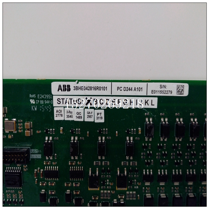
3BHE042816R0101模拟量卡件,PCD244A101培训教程
RECOM的RBBA3000是半砖封装的3kW升降压型转换器。该升降压技术提供9V至60V的输入电压,电流高达50A。它是车载网络的理想解决方案,例如,除了12V电路以外还有板载二次供电电路。RBBA3000也适合电池供电的设备或UPS(不间断电源)。发生电源故障时它可以使用48V电池来为设备供电,以帮助它完成当前任务然后返回到安全的位置。
")
3BHE042816R0101模拟量卡件,PCD244A101培训教程转换器的尺寸为63.2mm x 60.6mm x 13.0mm,体积50cm3。96%的超高效率让它可以有很紧凑的尺寸以及非常平坦的曲线图。转换器在轻载时也有出色的效率表现,但是在高功率密度下需进行冷却。将散热基板安装在半砖外壳的底板上可达到散热效果,因此转换器可在高达85°C的环境温度下全功率运行。超过此范围之后降额会是一个问题。在25°C和80%的负载下,根据Telcordia SR332计算MTBF为1.3 x 10⁶小时。
设定输出电压
依照以下计算公式,微调电阻器Rtrim可以设定RBBA3000的输出功率Ua:
设定了Rtrim后,可以按以下公式计算输出电压:
或者,可以在微调引脚施加特定电压来设定输出电压,公式如下:
改变电压Utrim时,RBBA3000的输出电压将按照图2所示的曲线进行调整。因此可以使用微控制器和DA,在0V至60V的范围内调节和控制输出电压,最大输出电流为50A。设定输出电压
限制电流
最大输出电流可以使用第二个电阻加以限制。它连接到Iset引脚,计算公式如下:
最大输出电流也可以由Iset引脚上的电压UItrim进行控制。电压也是可调的,与上述的电压设定相似。
测量电流
RBBA3000有内置电流测量功能,消除了电力电子电路中常见的电流测量问题。在Ishare引脚施加电压会提供电流信号实际电流的电流信号
并联电路
应用需要50A以上的电流时可以并联两个RBBA3000-50。并联时必须连接两个Ishare引脚以确保两个转换器的电流平均分配。另外,两个转换器的输入电压、输出电压、感测引脚等必须有相同的设置。
Therefore, it is necessary to map the physical address to the kernel space. Through virtul under Linux_ Address= (U32) ioremap (hpi_base, hpi_length) implementation. The main structure of the driver is as follows:
struct file_ operations hpi_ fops={owner:THIS_MODULE,read: hpi_read,write: hpi_write,poll : hpi_poll,open: hpi_open,release: hpi_release,};
The HPI communication protocol adopts the frame structure. Because the enhanced HPI interface allows access to all the RAM space inside the DSP, the system communication allocates 2 KB (16 bits) as the frame buffer in the DSP, and reads and writes 1 KB each. The protocol adopts one bit sliding window protocol. The frame format is listed in Table 1. Since microcontroller, microcontroller tends to have more special derivatives, more functions and lower technical threshold. Integrate more functions, larger memory and low power consumption.
For a given application, everyone is looking for the "best working state" to achieve the lowest cost, the smallest space and the smallest power consumption. In order to meet these needs, a new single chip microcomputer is debated. The final result is that the power supply voltage of the microcontroller continues to decrease.

