


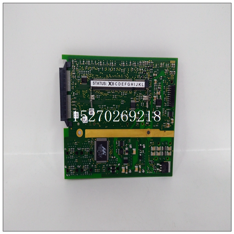
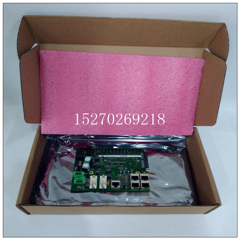
PDD200A101控制卡件,3BHE019633R0101使用配置说明
一个完美热管理的设备具有零热阻和无限的热耗散。然而,由于器件是由真实世界的材料制成的,每种材料都有自己独特的热阻特性,加上没有任何一个系统可以完美传递热量,因此系统设计人员必须从设计初期就设法优化每个关键器件的热性能。固定变量正如许多设计人员所知,应用的各种参数通常是固定的,所以需要开发设计以满足这些要求。在某些情况下,器件的效率、环境温度和系统的传热机制取决于最终应用。在许多情况下,器件如果要达到可接受的工作条件和低外壳温度,唯一的方法就是选择改善内部热设计和选择内部热阻较低的器件。
")
PDD200A101控制卡件,3BHE019633R0101使用配置说明优化的内部热阻
有两个关键参数可供检视,一个是器件的整体热阻而另一个是结温和环境温度之间的热阻 - Ψjt和θja。Ψjt和θja都是每个器件独一无二的热阻参数,并且会因封装的不同而异。Ψjt是热特性参数,用来测量热源和封装表面之间的多个热流路径,而θja代表热源和环境温度之间的直线热阻。Ψjt与功率相关,在更高的功耗和外壳温度下Ψjt的增加最终会降低器件的性能。即使优化了Ψjt,高θja电阻值也会导致外壳温度过高和受限的环境工作温度。有许多改善方式能够降低Ψjt和θja,例如材料优化、制造技术和不同的结到环境的热传递方法。其中一个降低热阻的最新进展是 3D Power Packaging?。 使用 3D Power Packaging? (3DPP) 技术,例如 FCOL、嵌入式 IC、散热孔等,RECOM 成功地大幅改善了Ψjt和θja值。通过降低 3DPP 产品的这些数值可以在不限制设备的环境温度的情况下达到更高的功率表现。高功率密度的解决方案如3DPP等产品,是专为高性能又高效的设备所设计,无需使用主动冷却或大型被动散热器。输入端存在雷击、浪涌或电压尖峰冲击
排查方案:可检查产品输入前端保险丝、整流桥、插件电阻等器件是否损坏,用差分测试上电波形分析。建议在符合技术手册EMS条件的环境内使用,若需使用在更恶劣环境,需在产品前端加入EMC滤波器、防浪涌器件。
输入电压远超产品最大规格值
interface. For c5416 and c5420dsp devices, their host interfaces are enhanced host interfaces. The standard HPI interface is an 8-bit bus interface. Two 8-bit bytes are combined to form a 16 bit byte. The enhanced HPI interface is divided into 8-bit and 16 bit. The operation sequence of the 8-bit enhanced host interface is the same as that of the standard HPI interface. The main difference is that the standard type can only access 2 kb of dedicated ram, while the enhanced type can access the entire RAM area of DSP. 16 bit enhanced HPI interface adopts 16 bit bus, and only one host operation can complete the access operation.
(2) HPI hardware connection
The interface circuit between HMS30C7202 and TMS320C5416 is shown in Figure 3. The system addresses all control registers, address registers and data registers of the HPI interface and maps them to the i/o memory space starting from the physical address 0x0c000000 of HMS30C7202.Use the address line ra[3:0] to generate the control signal required for HPI access. A0 and A1 determine the type of access register. A2 decides whether to access the first byte or the second byte: when A2 = 0, it means that the written data is the first byte; When A2 = 1, it means that the written data is the second byte. In hpi-8, all address lines and control lines are sampled on the falling edge of HDS1 and hds2, rather than determined by hr/w.

