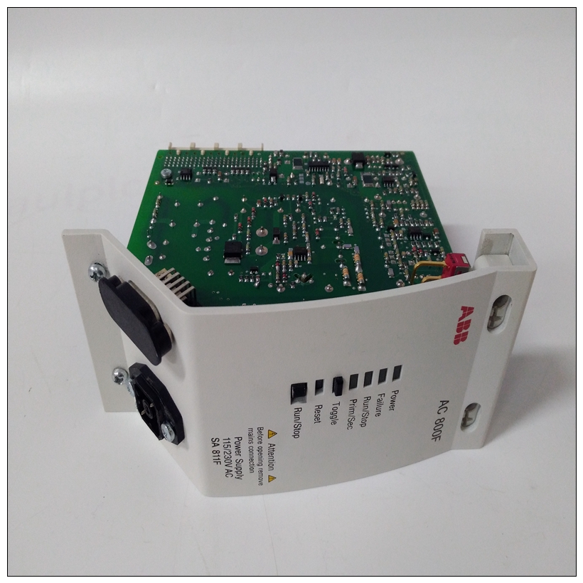
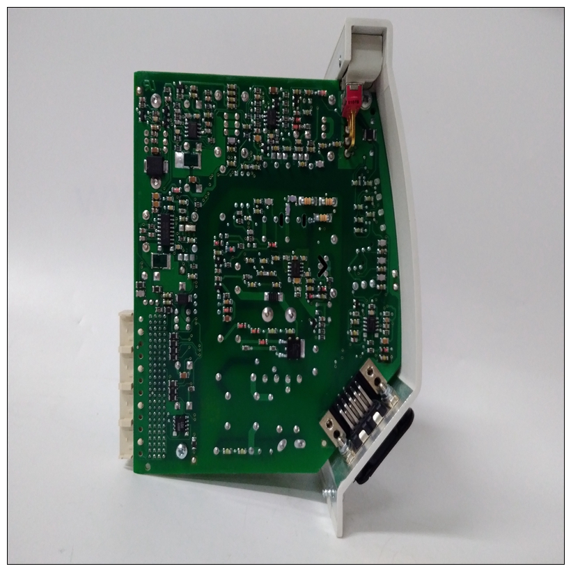
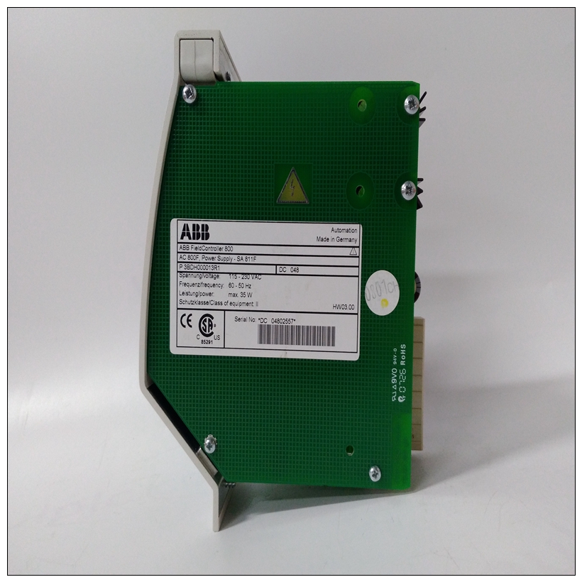
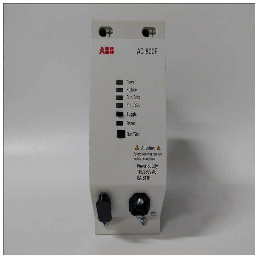
3BDH000017R1控制卡件,EI803F英文使用说明
由于支持通用的MODBUS RTU协议,所以能够在工控领域得到广泛应用。 数据格式:10位。1位起始位,8位数据位,1位停止位。 通讯地址(0~255)和波特率(300、600、1200、2400、4800、9600、19200、38400bps)均可设定;通讯网络最长距离可达1200米,通过双绞屏蔽电缆连接。 通讯接口高抗干扰设计,±15KV ESD保护,通信响应时间小于100mS。

3BDH000017R1控制卡件,EI803F英文使用说明抗干扰 可根据需要设置校验和。模块内部有瞬态抑制二极管,可以有效抑制各种浪涌脉冲,保护模块,内部的数字滤波,也可以很好的抑制来自电网的工频干扰。工业现场信号远程传输过程中,由于干扰源比较多,处理不当往往会影响正常的生产制造,造成不必要的损失,一些新的方案可以有效地提高现场控制的性能。先用ISO 4021将模拟信号转成数字信号,再用RS-485的数字信号进行远程传输,然后用远程模拟信号输出模块ISO DAO还原模拟信号输出,在工业现场中可以有效抑制干扰最新的嵌入式设计为各行各业及各种应用提供了大量复杂的新产品和新服务。由于精简成本的限制及提高性能的预期,嵌入式设计正在为各种包括家电、工具、建筑、服装及我们周围几乎所有物品在内的日常应用提供更小、更经济的解决方案。
这些嵌入式设计通常会由一个微控制器和各种二级接口构成,如电源。能够放心且迅速简便地选择电源的元器件对提供可靠的更小、更经济的解决方案至关重要。为实现这一目标,您需要使用直观的测试测量工具,快速获得优化结果。那么北京东方中科集成科技股份有限公司在多年与客户的交流及自我总结当中,整理出了此解决方案,仅供参考。本文重点介绍了电源分析实际应用,采用特定测量技术,为嵌入式设计更加高效地选择和确定相应的元器件。
电源分析
在本例中,我们要为开关电源选择最好的电源FET。可以根据FET的电流和开点电阻,相对简便地计算开关电源的静态损耗。晶体管的总功率损耗主要是开关损耗,开关损耗计算起来要困难得多。
本例的挑战是为这一应用选择最好的元器件,因为成本和功率损耗是一对矛盾。在这里,我们预先确定要测试的四个晶体管。
了实现计算机的自动测量与控制,越来越多的领域采用了A/D转换技术。随着大规模集成电路芯片技术的发展,速度更快、精度更高、使用更方便的集成电路芯片层出不穷。and the result will take effect immediately, and the result will be fed back to the front end for input without delay. For PLC, its core is a CPU. Like all computers, program instructions are executed in sequence and are scanned repeatedly. In the process of a scan, the subsequent results cannot be immediately used by the previous program, and they must wait until the next scan to be effective. Therefore, when compiling PLC programs, especially complex logic, there must be a clear concept of time sequence (time sequence, that is, according to the meaning of time sequence). When learning PLC, timing is an important content. For example, the automatic control of the drainage pump (only the automatically related i/o points are given), its working principle: the input has two switch signals of low liquid level and high liquid level (both are detected by the float switch. When the float is raised, the signal is high level, and when the float is lowered, the signal is low level), and the output is the signal of pump start. The ladder diagram in PLC only uses a simple program to realize the functions of high liquid level start and low liquid level stop. Its logic and working sequence for PLC


