


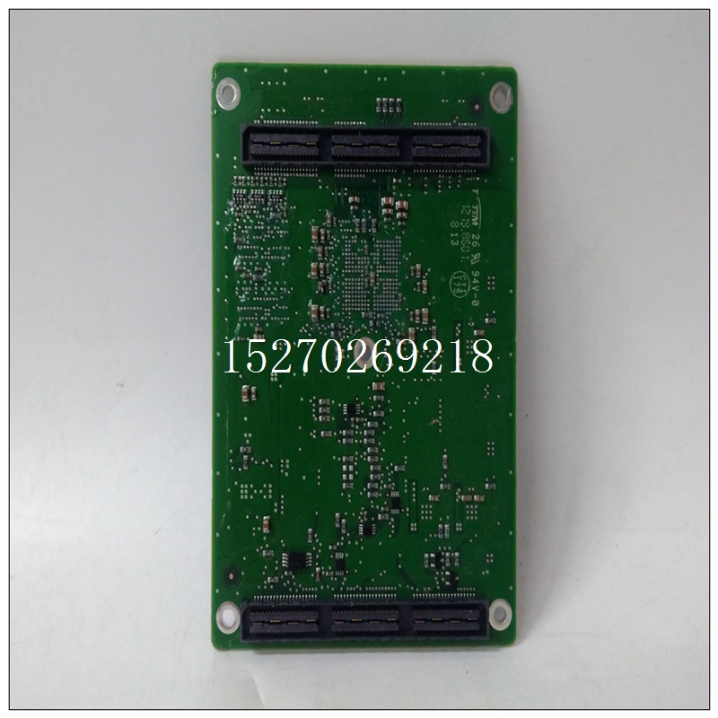
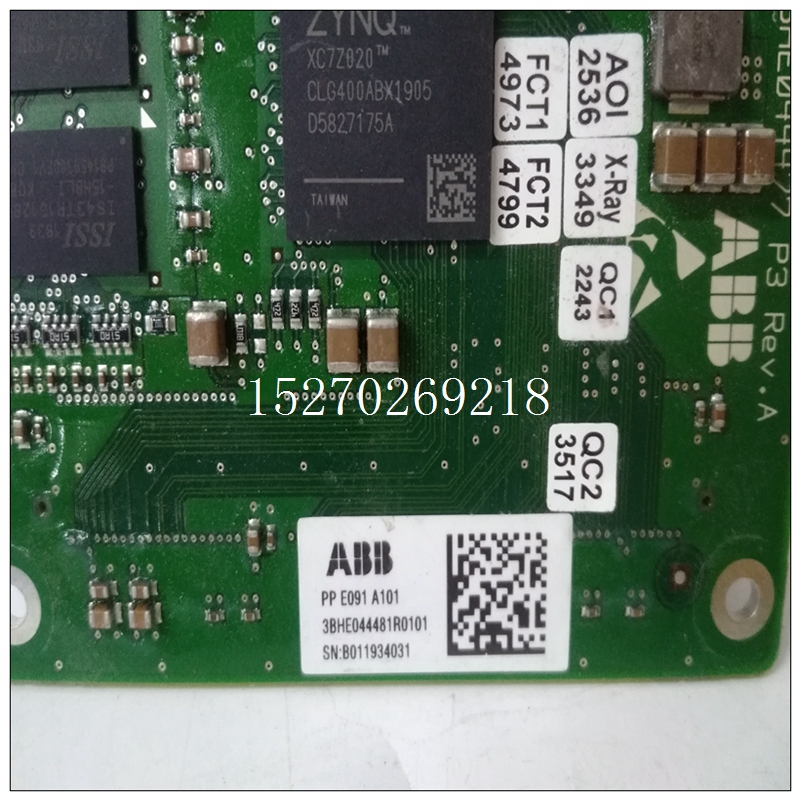
3BHE044481R0101产品尺寸,ABB模块
编程MC68230 PIITMC68230 PIIT的端口部分由三个8位端口和四个相关的握手信号。PIE模块允许每个8位端口中的每个位输入或输出,以及两条握手线。缓冲的VMIVME-2511选项在每个8位端口内仅允许一个方向,具有指定为端口C的端口除外。因此,8位和16位双向模式不能在缓冲Pl/T模块上编程。此外,如果位110在缓冲PIIT上选择模式,
")
3BHE044481R0101产品尺寸所有端口A数据方向寄存器位必须为为同一方向以及端口B数据方向编程登记位110模式和双向模式可用于无缓冲选项。下表和方框图将澄清这些陈述,并定义握手线路和端口C的编程。缓冲PIIT必须与VMIVME-2511的图和跳线选择一致,否则可能会损坏VMIVME-2511。见第5.2节。Plfl 110信道定义如表4-4所示。PI/T模块上可用的所有定时器模式都可以与VMIVME-2511。端口C引脚PCILTIN和PC2LTOUT专门缓冲作为输入和输出,分别用作定时器输入和定时器输出引脚。仅输出4.3.4中断编程可以利用Pl/T模块上可用的所有中断编程模式对于VMIVME-2511,前提是与中断相关的端口引脚是按此配置。见第5.2节。来自车载两个Pl/T模块的中断VMIVME-2511由MC68153 BIM生成。BIM的编程与中断有关的Pl/T模块应遵循图1所示的流程图4-1. 端口中断服务程序应遵循图4-2中的顺序。到对中断计时器进行编程,参见图4-3中的流程图。示例程序附录D中提供了详细的示例程序列表,以帮助用户编程此产品。附录Dl提供了一个测试的详细列表,该测试使用联锁握手模式将数据从P3传输到P4连接器。附录02提供了一个测试的详细列表,该测试验证了681 53 BIM集成电路。附录D3提供了一个测试的详细列表,该测试将数据写入端口A(P3连接器),中断HI状态握手线路,读取数据位于端口A(P4)上,并将数据存储在内存中。
PROGRAMMING THE MC68230 PIIT
The port section of the MC68230 PIIT consists of three 8-bit ports and four
associated handshake signals. The PIE modules allow each bit in each 8-bit port to be
either input or output, along with two of the handshake lines. The buffered
VMIVME-2511 option allows only one direction within each 8-bit port, with the
exception of the port designated as Port C. Therefore, the 8-bit and 16-bit bi-directional
modes cannot be programmed on the buffered Pl/T modules. In addition, if the bit 110
mode is chosen on the buffered PIIT, all Port A data direction register bits must be
programmed for the same direction, as well as those for the Port B data direction
register. Bit 110 mode and bi-direction mode may be used on the unbuffered option.
The following table and block diagram will clarify these statements as well as define
programming for the handshake lines and port C. The programming of the buffered
PIIT has to be consistent with the diagram and jumper selection of the VMIVME-2511,
otherwise damage to the VMIVME-2511 may result. See Section 5.2. The Plfl 110
channel definition is shown in Table 4-4. All timer modes available on the PI/T module can be utilized with the
VMIVME-2511. Port C pins PCILTIN and PC2LTOUT are specifically buffered as input
and output, respectively, for use as timer input and timer output pins.
Output only
4.3.4 INTERRUPT PROGRAMMING
All interrupt programming modes available on the Pl/T module can be utilized
with the VMIVME-2511, provided that those port pins associated with interrupts are
configured as such. See Section 5.2. Interrupts from the two Pl/T modules on-board
the VMIVME-2511 are generated by the MC68153 BIM. The programming of the BIM
and Pl/T modules concerning interrupts should follow the flowchart shown in Figure
4-1. The port interrupt service routine should follow the sequence in Figure 4-2. To
program the timers for interrupts, see the flowchart in Figure 4-3.
SAMPLE PROGRAMS
Detailed sample program listings are provided in Appendix D to assist the user in
programming this product. Appendix Dl provides a detailed listing of a test that
transfers data from the P3 to P4 connector using the interlocked handshake mode.
Appendix 02 provides a detailed listing of a test that verifies all interrupt levels of the
681 53 BIM integrated circuit. Appendix D3 provides a detailed listing of a test that
writes data to port A (P3 connector), interrupts on the HI status handshake line, reads
data in on Port A (P4) and stores data in memory.

