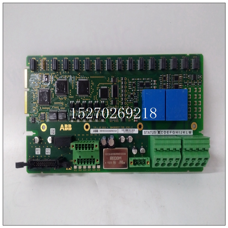
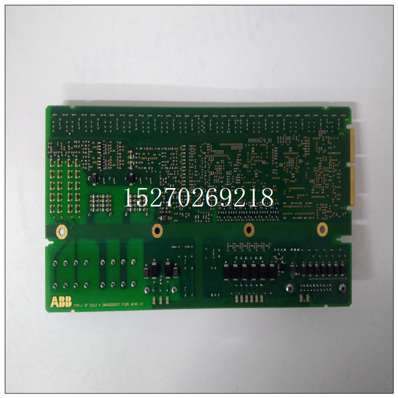
3BHE020357P201产品外观,ABB输入卡件
登记结果位置必须包含用户编程的四个字节数据这四个字节的数据驻留在异常向量表中,并指向中断服务例程的位置。中断服务例程读取数据来自双端口寄存器,然后返回主程序。
4.4.10外部触发操作电路板可以响应外部TTL脉冲(激活需要低或“零”脉冲)单个a/D转换或a/D转换扫描将启动。首先,用户通过向CSR和选择随机模式或扫描模式,但不设置EN启动CSR中的转换H位(D13)。

3BHE020357P201产品外观控制位ENA EXT STRT H(D11)必须改为设置为“一”。这将在P2外产生TTL高电平(逻辑“1”)连接器引脚A31,用于向外部设备发送信号,表明电路板已准备好接收外部触发器。至少100纳秒的外部逻辑电平(“零”)触发脉冲然后可以通过P2连接器引脚A27输入到电路板。这将启动A/D转换取决于先前选择的A/D模式。除了启用外部触发器操作外,还有一些必须安装跳线,以将P2连接器引脚电气连接到外部触发电路。关于选择这些跳线,请参阅第5.4.4节。是请注意,其他板有时会使用P2输入/输出引脚来执行不同的操作输入/输出功能。这需要从系统角度进行检查,以验证是否存在没有多个驱动器/接收器使用这些P2输入/输出线:P2-A31、A32、A27和A28。4.5更改A/D操作模式电路板在自动扫描模式下通电。切换进入任何其他A/D操作模式时,必须执行软件重置顺序在重新编程新的A/D操作模式之前执行。此序列包括:(1)写入控制字,设置软件复位H(D9)位和新的A/D模式(D8到D6),(2)写入控制字以清除软件重置H(D9)位,包括新的A/D模式(D8到D6),(3) 接下来重写A/D模式,并在控件中设置EN START CONV H(D13)word启动A/D转换序列。
只有在切换到操作模式时,才需要上述顺序自动扫描模式以外的模式。任何其他模式开关都可以通过改变控制中的模式位(D8到D6)直接编程登记表4.5-1显示了要切换到的正确顺序和控制字其他四种A/D操作模式。
Register. The resulting location must contain a user-programmed four bytes of
data. These four bytes of data reside in the exception vector table and point to the
location of the Interrupt Service routine. The Interrupt Service routine reads in the
data from the dual port registers and then returns to the main program.
4.4.10 External Trigger Operation
The board may be enabled to respond to an external TTL pulse (active
low or "zero" pulse required) a single A/D conversion or a scan of A/D conversions
will be initiated. First, the user selects the A/D mode to be used by writing to the
CSR and selecting a RANDOM MODE or SCANNING MODE, but do not set the EN
START CONV H bit (D13) in the CSR. The control bit ENA EXT STRT H (D11)
must be set to a "one" instead. This will generate a TTL high (logic "one") out the P2
connector pin A31 to signal the external equipment that the board is ready to receive
an External Trigger. An external logic level ("zero") trigger pulse of at least 100 ns
may then be input to the board via the P2 connector pin A27. This will start the A/D
conversion(s) depending on the A/D Mode which was previously selected.
In addition to enabling the External Trigger operation there are some
jumpers which must be installed to electrically connect the P2 connector pins to the
External Trigger circuitry. Refer to Section 5.4.4 on selecting these jumpers. Be
aware that the P2 I/O pins are sometimes used by other boards to perform different
I/O functions. This needs to be checked from a system viewpoint to verify there are
not multiple drivers/receivers using these P2 I/O lines: P2-A31, A32, A27, and A28.
4.5 CHANGING A/D OPERATING MODES
The board powers up in the AUTO SCANNING MODE. To switch the
board into any of the other A/D operating modes, a software reset sequence must be
performed before reprogramming the new A/D operating mode. This sequence
includes: (1) writing a control word setting the SOFTWARE RESET H (D9) bit and
the new A/D Mode (D8 through D6), (2) writing a control word clearing the
SOFTWARE RESET H (D9) bit and including the new A/D mode (D8 through D6),
(3) next rewrite the A/D mode and set the EN START CONV H (D13) in the control
word to start the A/D conversion sequence.
The above sequence is only necessary when switching to an operating
mode other than the AUTO SCANNING MODE. Any other mode switch can be
directly programmed by changing the mode bits (D8 through D6) in the Control
Register.
Table 4.5-1 shows the proper sequence and control words to switch to
the four other A/D operating modes.


