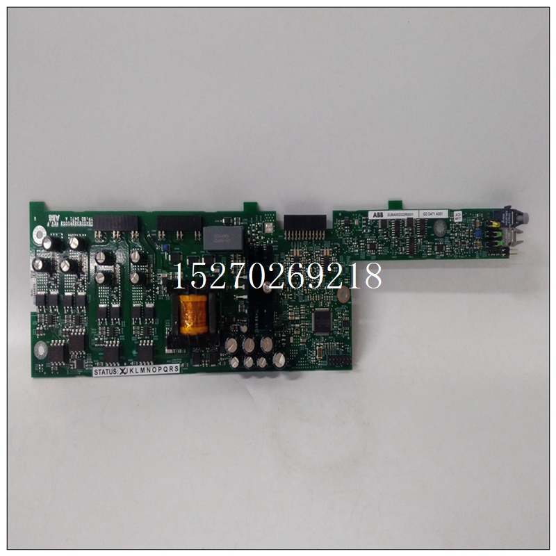
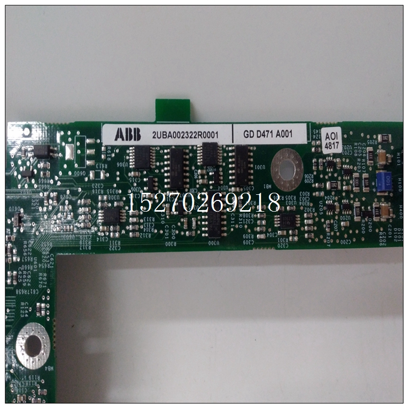
2UBA002322R0001中文PDF用户手册,ABB模块卡件
扫描中断模式对输入进行单次扫描然后停止操作,与扫描轮询模式相同。相反在状态寄存器中设置标志位时,会向总线生成一个信号中断器模块(68153),用于向CPU板生成VMEbus中断。总线中断器模块(68153)必须事先编程为生成此VMEbus中断,并在CPU板生成的中断确认周期。编程总线断续器模块(68153)详见第4.4.7节。

2UBA002322R0001中文PDF用户手册扫描中断模式可与用于执行定期数据记录的可编程定时器(8254)。要做到这一点如第4.4.6节所述,需要设置定时器和中断器芯片通过4.4.9。CSR的控制字必须有位10(COUNT STARTH)设置而不是位13(EN START CONV H)。除了CPU低之外开销,该模式将VMIVME-3112上的数字活动最小化转换。
要进入扫描中断模式,以下CSR位必须设置:随机轮询模式随机轮询模式是控制A/D转换。CPU板写入控制寄存器,选择使用控制寄存器位MUX A5H到MUX A0H转换的通道D5到D0)。然后,CPU必须设置EN START CONV H位(D13),该位启动多路复用器采集和ADC时序,详见3.5节。然后,CPU必须轮询状态中的新数据RDY H位(D15)登记当该标志变高时,A/D转换完成,数据已存储在随机转换数据寄存器(RCDR)中。CPU然后,电路板读取该数据并选择下一个要转换的通道。这当需要转换的通道不是按顺序排列时,模式很有用,因此,可以按随机顺序选择通道。在某些情况下,它也很有用频道必须比其他频道更频繁地转换。每次打开一个新频道时选择A/D转换时,模式控制位必须设置为随机位轮询模式。必须设置以下CSR位:随机中断模式随机中断模式的操作与随机中断模式相同上述轮询模式。唯一的区别是CPU收到的信号是A/D转换由车载系统生成的VMEbus中断完成总线断续器模块(68153)。总线中断模块必须编程在第一次转换完成之前。然后在每次中断后总线断路器模块必须通过一次负载操作重新启用。提到第4.4.8节和第4.4.9节了解有关总线断路器编程的更多信息单元每次选择新通道进行a/D转换时,模式控制位必须设置为随机中断模式。以下CSR必须设置位:
The SCANNING INTERRUPT MODE performs a single scan of the input
channels, then stops operating, the same as the SCANNING POLL MODE. Instead
of setting a flag bit in the Status Register, a signal is generated to the Bus
Interrupter Module (68153) which generates a VMEbus Interrupt to the CPU board.
The Bus Interrupter Module (68153) must have previously been programmed to
generate this VMEbus Interrupt and also to respond with an 8-bit vector during the
Interrupt Acknowledge cycle generated by the CPU board. Programming of the
Bus Interrupter Module (68153) is detailed in Section 4.4.7.
The SCANNING INTERRUPT MODE can be used along with the
Programmable Timer (8254) to perform periodic data logging. To do this, it is
necessary to set up the timer and interrupter chips as described in Sections 4.4.6
through 4.4.9. The control word for the CSR must have bit 10 (COUNT STARTH)
set instead of bit 13 (EN START CONV H). In addition to having low CPU
overhead, this mode minimizes digital activity on the VMIVME-3112 during
conversions.
To enter the SCANNING INTERRUPT MODE the following CSR bits must
be set :
RANDOM POLLING MODE
The RANDOM POLLING MODE is the traditional method of controlling an
A/D conversion. The CPU board writes to the Control Register selecting the
channel to be converted using Control Registers bits MUX A5H through MUX A0H
(D5 through D0). The CPU must then set the EN START CONV H bit (D13), which
starts the multiplexer acquisition, and ADC timing sequence which was detailed in
Section 3.5. The CPU must then poll the NEW DATA RDY H bit (D15) in the Status
Register. When this flag goes high, the A/D conversion is complete and the data
has been stored in the Random Conversion Data Register (RCDR). The CPU
board then reads this data and selects the next channel to be converted. This
mode is useful when channels desired to be converted are not in sequential order,
thus channels can be selected in a Random order. It is also useful when some
channels must be converted more often than others. Each time a new channel is
selected for A/D Conversion, the Mode Control bits must be set to the RANDOM
POLLING MODE. The following CSR bits must be set: RANDOM INTERRUPT MODE
The RANDOM INTERRUPT MODE operates the same as the RANDOM
POLLING MODE described above. The only difference is that CPU is signaled that
the A/D conversion is complete by a VMEbus Interrupt generated by the on-board
Bus Interrupter Module (68153). The Bus Interrupt Module must be programmed
before the first conversion is completed. Then after each interrupt is serviced the
Bus Interrupter Module must be re-enabled by one load operation. Refer to
Sections 4.4.8 and 4.4.9 for more information on programming the Bus Interrupter
Module. Each time a new channel is selected for A/D conversion, the Mode
Control bits must be set to the RANDOM INTERRUPT MODE. The following CSR
bits must be set:


