


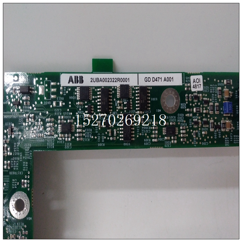
GDD471A001使用说明,ABB自动化模块
初始化当系统重置应用于电路板时,控制寄存器和所有模数转换器(ADC)标志被清除为低状态“零”。一通过设置软件重置,可以生成独立板重置将控制位设置为“1”。电路板将保持复位,直到软件复位位已清除。4.4控制和读取模数转换器数据VMIVME-3112具有许多功能,允许电路板用于各种应用。最简单的操作模式是自动通电时自动进入的扫描模式。
")
GDD471A001使用说明4.4.1自动扫描模式该模式在通电时进入,或者CSR可编程为进入此模式。自动扫描模式允许用户操作无需在CSR中设置任何控制位,也无需选择每个控制位要转换的通道。通电时,VMIVME-3112启动转换通道0并通过所需的最后一个通道顺序执行转换,然后在通道0处再次开始。每次转换后,该通道的数据存储在一种双端口寄存器,VMEbus也可以访问该寄存器,并且可以在任何时间读取该寄存器时间跳线字段J6控制扫描的通道数。请参阅第节5用于这些跳线的配置。增益放大器必须设置为增益自动扫描模式中的“一”。必须至少有16个通道在板上安装过滤器时扫描。参考第3.6.1节。
每次扫描连接的输入通道都会产生数字化数据写入扫描数据寄存器,从而覆盖前一个扫描每次执行读取时,都会收到最新的数据。要进入自动扫描模式(通电时自动进入),必须设置以下CSR位:扫描轮询模式扫描轮询模式对输入进行单次扫描通道,但在最后一个通道数字化后停止扫描过程。然后在状态寄存器中设置REGD扫描结束H标志(位D13)。轮询该位允许CPU板确定扫描何时完成已完成,扫描数据寄存器已更新数据。可编程定时器(8254)可以被设置为周期性地生成启动扫描轮询模式的信号。例如,计时器可以是编程为每秒产生一次脉冲,开始扫描。这个CPU仍然必须轮询扫描H位的REGD端,直到它变高,因此扫描中断模式更适合与计时器一起使用。这个可编程定时器(8254)编程注意事项详见第4.4.6节。
INITIALIZATION
When SYSTEM RESET is applied to the board, the Control Register and
all Analog-to-Digital Converter (ADC) flags are cleared to the LOW state "zero". An
independent BOARD RESET can be generated by setting the SOFTWARE RESET
control bit to a "one". The board will remain reset until the SOFTWARE RESET bit
is cleared.
4.4 CONTROLLING AND READING THE ANALOG-TO-DIGITAL CONVERTER
DATA
The VMIVME-3112 has a number of features which allow the board to be
used in a variety of applications. The simplest mode of operation is the AUTO
SCANNING MODE which is automatically entered at power-up.
4.4.1 AUTO SCANNING MODE
This mode is entered at power-up, or the CSR may be programmed to
enter this mode. The AUTO SCANNING MODE allows the user to operate the
board without setting any control bits in the CSR and without selecting each
channel to be converted. On power-up the VMIVME-3112 initiates a conversion on
CH 0 and sequentially performs conversions through the last channel desired, then
begins again at CH 0. After each conversion, the data for that channel is stored in
a dual port register which is also accessible to the VMEbus and may be read at any
time. Jumper field J6 controls how many channels are scanned. Refer to Section
5 for configuration of these jumpers. The gain amplifier must be set to a gain of
"one" in the AUTO SCANNING MODE. A minimum of 16 channels must be
scanned when filters are installed on the board. Refer to Section 3.6.1.
Every scan of the connected input channels results in digitized data
written to the SCAN DATA registers, thus, overwriting the data from the previous
scan. Any time a read is performed the latest data is always received.
To enter the AUTO SCANNING MODE (automatically entered at power-up),
the following CSR bits must be set:SCANNING POLL MODE
The SCANNING POLL MODE performs a single scan of the input
channels, but stops the scanning process after the last channel has been digitized.
The REGD END OF SCAN H flag (bit D13) is then set in the Status Register. Polling this bit allows the CPU board to determine when the scan has been
completed and the SCAN DATA registers have updated data. The Programmable Timer (8254) may be set to periodically generate a
signal which starts the SCANNING POLL MODE. For example, the timer may be
programmed to generate a pulse once every second which starts the scan. The
CPU must still poll the REGD END OF SCAN H bit until it goes high, so the
SCANNING INTERRUPT MODE is a better candidate for use with the timer. The
Programmable Timer (8254) programming considerations are detailed in
Section 4.4.6.

