


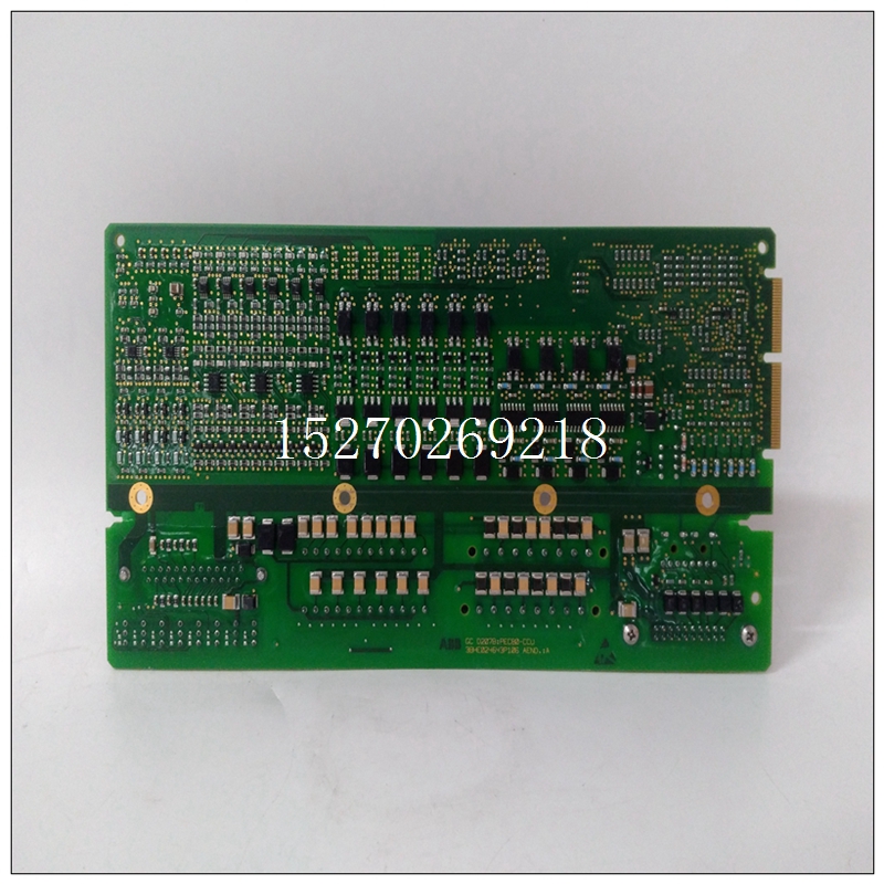
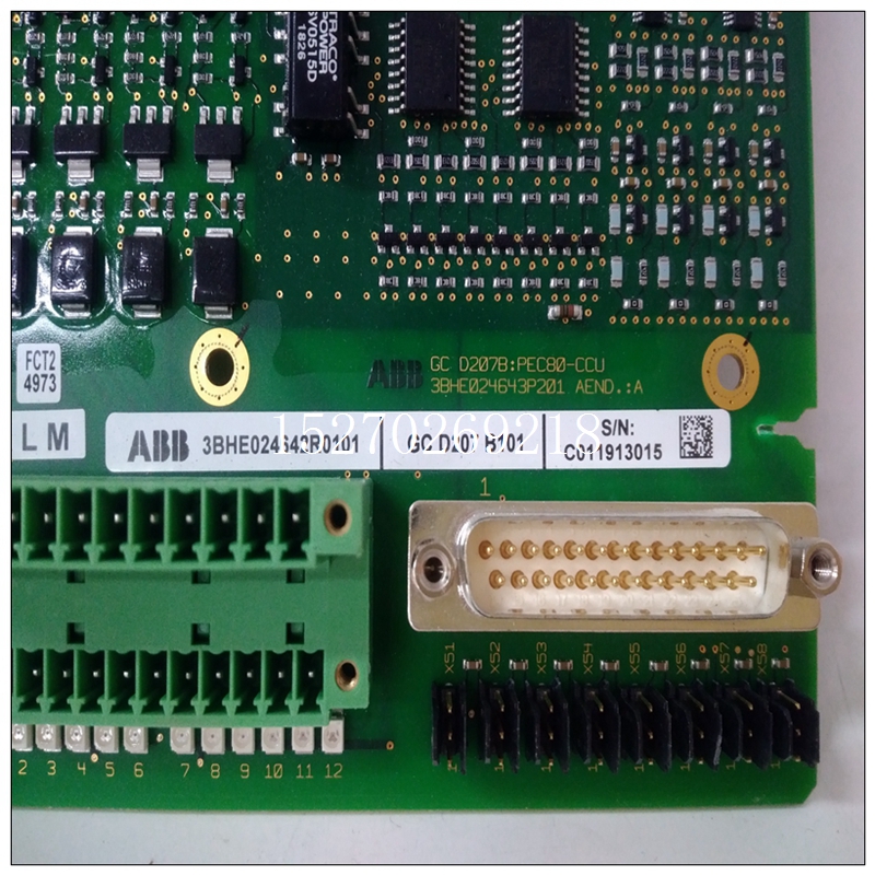
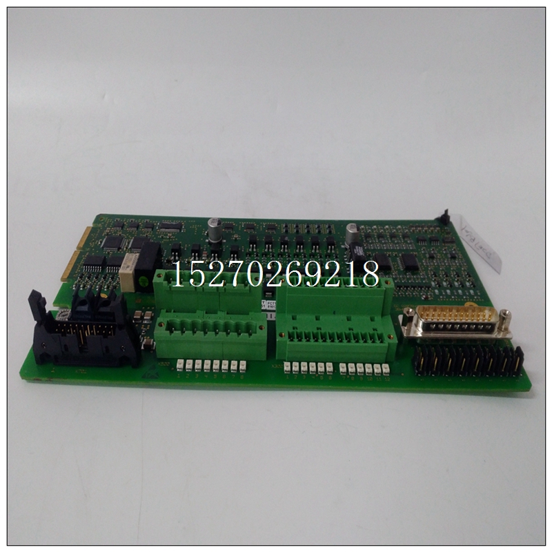
3BHE024642R0101中文使用说明,ABB工业卡件
解决延迟直接发生在系统发生状态变化之后模拟网络(例如选择新的输入通道),并表示网络的稳定时间。结算延迟完成后跟踪保持放大器(图1.2-1)进入跟踪模式,并且跟踪间隔开始。在跟踪间隔期间,T和H的输出放大器设置为等于其输入电压的值。在跟踪间隔结束时,T和H放大器进入保持模式,在该模式下,放大器的输出保持在恒定水平,以及转换来自定时解码器的CMD导致A/D转换开始。
")
3BHE024642R0101中文使用说明A/D转换将T&H放大器的输出数字化为12位数据字,以及然后终止转换序列。ADC的CONV COMPL L标志在转换期间为高,否则为低。在随机轮询模式下,完成A/D转换会导致将新数据RDY标志设置为高,表示有效数据存在于随机转换器数据寄存器(RCDR)(第4节)。阅读的动作RCDR重置CSR中的新数据RDY和CONV COMPL L标志。如果转换是扫描中要转换的最后一个通道轮询模式,然后在控制和状态中设置标志(扫描H的REGD END)注册(CSR)。可以读取该标志以确定所有通道都已已转换并存储,可供读取。
3.6模拟输入有64个差分或单端模拟输入通道可从两个前面板连接器获得。建议差速器模式用于增加噪声和共模抑制。未使用的输入应接地。这包括差分输入的低端。为了正确操作时,高压侧和低压侧输入必须在VME的±12 V范围内底盘接地。3.6.1低通滤波器和输入多路复用器64个模拟输入通道可以配备单独的单极低通滤波器,如图3.6.1-1所示,并且可以由用户配置为单端或差分操作。输入滤波器见第2.3.2节规范。为了通过滤波模拟输入实现最大系统精度,需要每个通道的采样率应限制在2000 Hz或更低。更高的样本速率将在输入端产生反射的“泵回”电流,从而导致滤波器输入电阻器上的错误电压。这意味着当过滤器安装后,至少可以在自动模式下连续扫描16个通道扫描模式。
The settling delay occurs directly after a state-change has occurred in the
analog networks (such as selecting a new input channel), and represents the
settling time of the networks. After the settling delay has been completed, the
Track-and-Hold (T&H) amplifier (Figure 1.2-1) enters the TRACKING MODE, and
the tracking interval begins. During the tracking interval, the output of the T&H
amplifier settles to a value which is equal to its input voltage.
At the end of the tracking interval, the T&H amplifier enters the HOLD
MODE, in which the output of the amplifier is held at a constant level, and a CONV
CMD from the timing decoder causes the A/D conversion to begin. The A/D
conversion digitizes the output of the T&H amplifier into a 12-bit data word, and
then terminates the conversion sequence. The CONV COMPL L flag from the ADC
is HIGH during the conversion, and is LOW otherwise.
In the RANDOM POLL MODE, completion of the A/D conversion causes
the NEW DATA RDY flag to be set HIGH, indicating that valid data is present in the
Random Converter Data Register (RCDR) (Section 4). The action of reading the
RCDR resets the NEW DATA RDY and CONV COMPL L flag in the CSR. If the conversion is the last channel to be converted in the SCANNING
POLL MODE, then a flag (REGD END OF SCAN H) is set in the Control and Status
Register (CSR). This flag may be read to determine that all channels have been
converted and stored and are available to be read.
3.6 ANALOG INPUTS
Sixty-four differential or single-ended analog input channels are
available from two front panel connectors. It is recommended that the differential
mode be used for increased noise and common mode rejection. Unused inputs
should be grounded. This includes the low-side of differential inputs. For correct
operation, both the high-side and low-side inputs must be within ±12 V of the VME
chassis ground.
3.6.1 Low Pass Filters and Input Multiplexers
The 64 analog input channels can be provided with individual, singlepole, low pass filters as shown in Figure 3.6.1-1, and can be user-configured to
operate either single-ended or differentially. See Section 2.3.2 for input filter
specifications.
To achieve maximum system accuracy with filtered analog inputs, the
sample rate should be limited to 2,000 Hz or less per channel. Higher sample
rates will produce reflected "pump back" currents at the inputs which can induce
error voltages across the filter input resistors. This implies that when filters are
installed, a minimum of 16 channels can be continuously scanned in the AUTO
SCAN MODE.

