


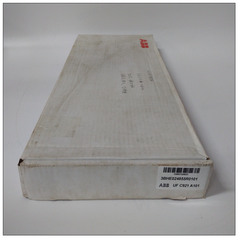
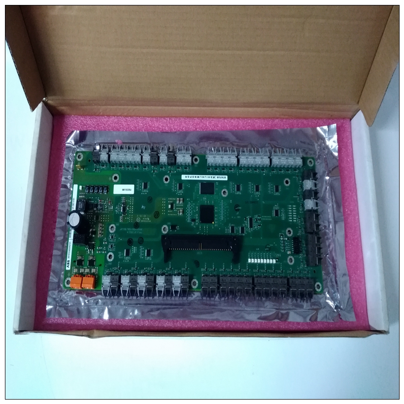
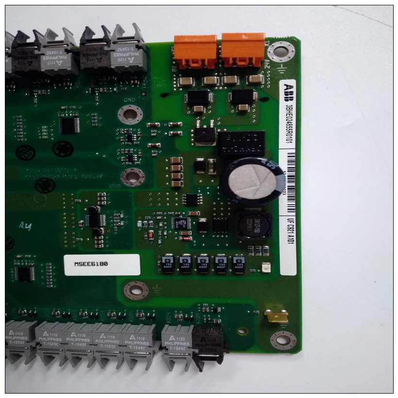
3BHE024855R0101培训教程,ABB控制卡件
调试连接器(J2)190针连接器(MVME2700基板上的J2)提供访问权限到处理器总线(MPU总线)和一些网桥/内存控制器信号。它可以用于调试目的。引脚分配为如下表所示。软盘/LED连接器(J3)一个50针高密度连接器(MVME2700基板上的J3)提供基板和可选外部接口之间的接口软盘驱动器。
")
3BHE024855R0101培训教程除了磁盘驱动器控制信号外,还有一组16个线路可用于驱动外部LED阵列PCI扩展连接器(J4)MVME2700具有将PMC载波板堆叠在用于额外PCI扩展的基板。114针接头(J4位于基板)提供MVME2700和载体之间的接口板四个64针连接器(MVME2700上的J11/12/13/14)为基板和可选PCI夹层卡之间的接口(PMC)。引脚分配在接下来两页的表格中列出。注:根据IEEE标准,每个PMC可以获得最大7.5W的功率P1386.1规范。这可以与任何单个PMC电压一起使用(+3.3V、+5V或+12V)或任何组合,只要总数为每个PMC插槽不超过7.5W。1下表总结了特定于配置用于MVME712M的MVME2700模块过渡模块。
VMEbus连接器P2两个160针接头(P1和P2)提供MVME2700和VMEbus。P1为24位寻址和16位数据提供电源和VME信号。其引脚分配由VMEbus规范设置。P2行A、C、Z和D向MVME712M过渡模块。P2 B行为MVME2700提供电源,具有上面的八条VMEbus地址线,以及额外的16条VMEbus数据线。MVME712M输入/输出中P2的引脚分配配置如表4-10所示。串行端口1-4MVME2700提供异步(端口1和2)和同步/异步(端口3和4)串行连接,
使用四个EIA-232-D DB25连接器(J7-J10)实现。这些连接器位于MVME712M过渡段的前面板上
单元
Debug Connector (J2)
A 190-pin connector (J2 on the MVME2700 base board) provides access
to the processor bus (MPU bus) and some bridge/memory controller
signals. It can be used for debugging purposes. The pin assignments are
listed in the following table.Floppy/LED Connector (J3)
A 50-pin high-density connector (J3 on the MVME2700 base board)
supplies the interface between the base board and an optional external
floppy disk drive. In addition to the disk drive control signals, a set of 16
lines is available to drive an external LED arrayPCI Expansion Connector (J4)
The MVME2700 has provision for stacking a PMC carrier board on the
base board for additional PCI expansion. A 114-pin connector (J4 on the
base board) supplies the interface between the MVME2700 and the carrier
board.Four 64-pin connectors (J11/12/13/14 on the MVME2700) supply the
interface between the base board and an optional PCI mezzanine card
(PMC). The pin assignments are listed in the tables on the next two pages.
Note Each PMC can draw a maximum of 7.5W of power, per the IEEE
P1386.1 Specification. This can be with any single PMC voltage
(+3.3V, +5V, or +12V) or any combination, as long as the total
does not exceed 7.5W per PMC slot.1The next tables summarize the pin assignments of connectors specific to
MVME2700 modules that are configured for use with MVME712M
transition modules.
VMEbus Connector P2
Two 160-pin connectors (P1 and P2) supply the interface between the
MVME2700 and the VMEbus.
P1 provides power and VME signals for 24-bit addressing and 16-bit data.
Its pin assignments are set by the VMEbus specification.
P2 rows A, C, Z, and D provide power and interface signals to the
MVME712M transition module. P2 row B supplies the MVME2700 with
power, with the upper eight VMEbus address lines, and with an additional
16 VMEbus data lines. The pin assignments for P2 in the MVME712M I/O
configuration are listed in Table 4-10.Serial Ports 1-4
The MVME2700 provides both asynchronous (ports 1 and 2) and
synchronous/asynchronous (ports 3 and 4) serial connections,
implemented with four EIA-232-D DB25 connectors (J7-J10). These
connectors are located on the front panel of the MVME712M transition
module.

