


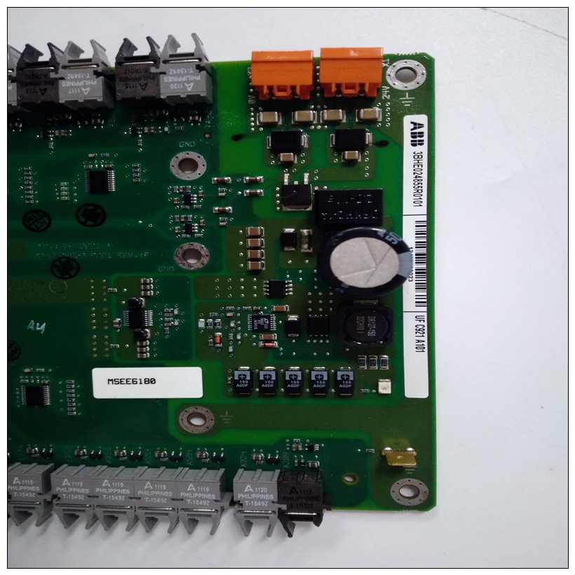
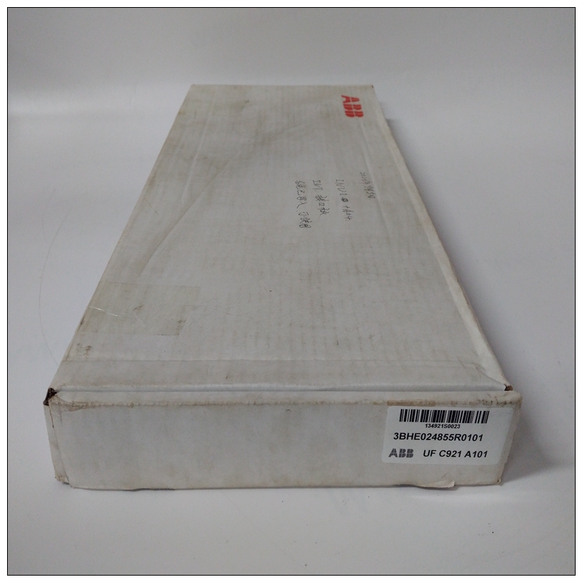
UFC921A101输出模块,ABB怎么使用
P2适配器板的功能包括:
❏ 50针(3排VME背板)或68针(5排VME背板)背板)连接至MVME761和/或的SCSI电缆连接器其他SCSI设备❏ 跳线可选有源SCSI端接电阻器
❏ 由+5V直流电源开发的熔断SCSI终端电源接头P2处
❏ 连接至MVME761的64针VME连接器串行接口模块
")
UFC921A101输出模块MVME761上的同步串行端口可通过串行端口配置接口模块(SIM),与适当的跳线一起使用
过渡模块和基板上的设置。SIM是小型插件印刷电路板,包含转换所需的所有电路TTL电平端口,用于各种工业标准串行接口(如EIA-232、EIA-530等)所需的标准电压电平。SIM是可用于以下配置:本章总结了以下几组的引脚分配:MVME2700的互连信号:
❏ 具有MVME712M通用引脚分配的连接器作为MVME761兼容版本的基板,下表仅提供引脚分配。有关详细信息有关各种互连信号的说明,请咨询支持部门MVME2700单板的信息文档包计算机或过渡模块的支持信息部分必要时提供文件。
通用连接器❏ 具有特定于MVME761的引脚分配的连接器-基板的兼容版本下表描述了使用相同引脚的连接器MVME712M和MVME761兼容版本的作业基板的。LED夹层连接器(J1)
14针连接器(基板上的J1)提供基板和LED夹层模块。在基板上连接器是一个2x7头。在LED夹层上,它是一个2x7表面安装插座条。卸下LED夹层可以使用夹层连接器用作远程状态和控制连接器。在此应用中,J1可以连接到用户提供的外部电缆,以将重置和中止信号以及LED线路传输到位于MVME2700。最大电缆长度为15英尺。引脚分配为
The features of the P2 adapter board include:
❏ A 50-pin (3-row VME backplane) or 68-pin (5-row VME
backplane) connector for SCSI cabling to the MVME761 and/or to
other SCSI devices❏ Jumper-selectable active SCSI terminating resistors
❏ Fused SCSI terminator power developed from the +5V DC present
at connector P2
❏ A 64-pin VME connector to the MVME761
Serial Interface Modules
The synchronous serial ports on the MVME761 are configurable via serial
interface modules (SIMs), used in conjunction with the appropriate jumper
settings on the transition module and base board. The SIMs are small plugin printed circuit boards which contain all the circuitry needed to convert
a TTL-level port to the standard voltage levels needed by various industrystandard serial interfaces, such as EIA-232, EIA-530, etc. SIMs are
available for the following configurations:This chapter summarizes the pin assignments for the following groups of
interconnect signals for the MVME2700:
❏ Connectors with pin assignments common to MVME712M as well
as MVME761-compatible versions of the base boardThe following tables furnish pin assignments only. For detailed
descriptions of the various interconnect signals, consult the support
information documentation package for the MVME2700 single board
computer or the support information sections of the transition module
documentation as necessary.
Common Connectors❏ Connectors with pin assignments specific to MVME761-
compatible versions of the base board
The following tables describe connectors used with the same pin
assignments by MVME712M- as well as MVME761-compatible versions
of the base board.LED Mezzanine Connector (J1)
A 14-pin connector (J1 on the base board) supplies the interface between
the base board and the LED mezzanine module. On the base board, this
connector is a 2x7 header. On the LED mezzanine, it is a 2x7 surfacemount socket strip.
Removing the LED mezzanine makes the mezzanine connector available
for service as a remote status and control connector. In this application, J1
can be connected to a user-supplied external cable to carry the Reset and Abort signals and the LED lines to a control panel located apart from the
MVME2700. Maximum cable length is 15 feet. The pin assignments are
as follows:

