


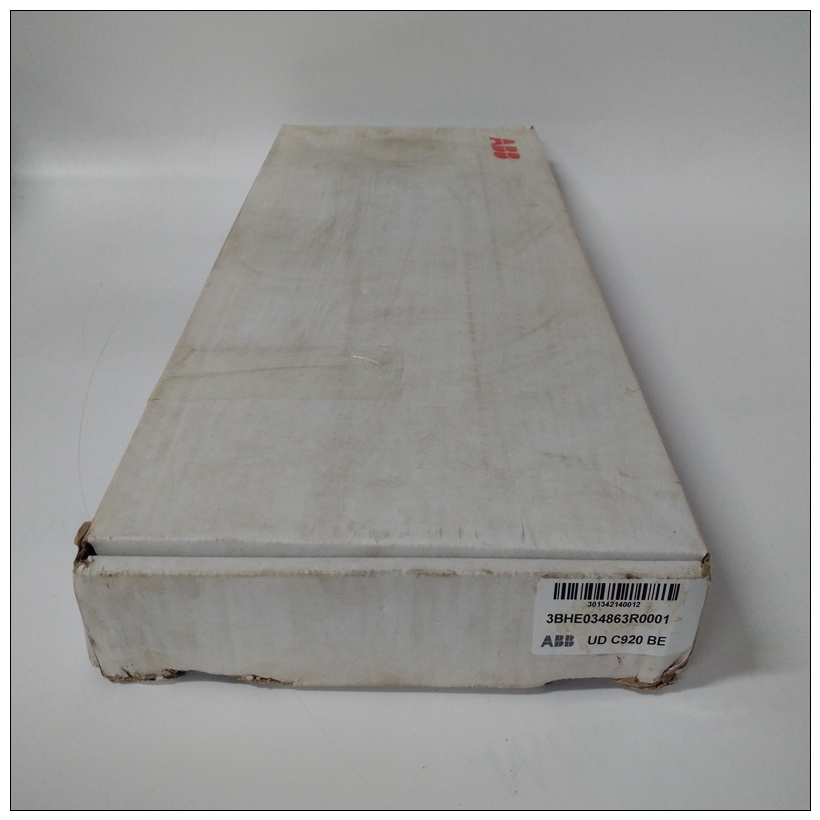
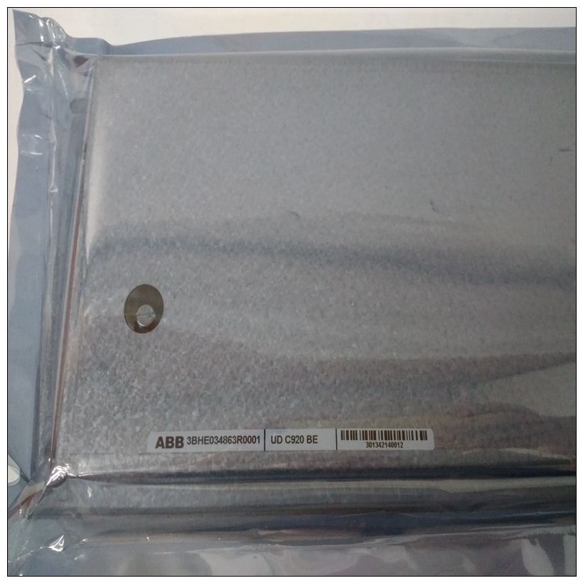
3BHE034863R0001接口控制模块,ABB如何使用
ECC DRAM由Falcon内存控制器芯片组控制。Falcon ASIC执行双向交织,具有双位错误检测和单位错误校正。RAM200模块可用于下表列出了MVME2700内存扩展。除了ECC DRAM之外,RAM200模块还向两组(A和B)中的8MB额外64位闪存。跳投者标头(J9)告诉Falcon芯片组在内存中取板的位置重置向量。根据J9的配置,重置执行来自闪存组A或B。
")
3BHE034863R0001接口控制模块MVME712M过渡模块MVME712M过渡模块(图1-3)和P2适配器板是与MVME2700 VME模块的型号一起使用。MVME712M的特点包括:
❏ 并行打印机端口(通过P2适配器)❏ 支持AUI连接的以太网接口(通过P2适配器)
❏ 四个EIA-232-D多协议串行端口(通过P2适配器)❏ SCSI接口(通过P2适配器)用于连接到两个内部和外部设备❏ 插座安装的SCSI端接电阻器,用于电缆末端或中间电缆配置
❏ 调制解调器连接规定❏ SCSI终端电源的绿色LED;以太网黄色LED收发器功率P2适配器板的功能包括:❏ 一个50针连接器,用于SCSI布线至MVME712M和/或其他SCSI设备
❏ 插座安装的SCSI端接电阻器,用于电缆末端或中间电缆配置
❏ 由+5V直流电源开发的熔断SCSI终端电源接头P2处
❏ 一个64针DIN连接器,用于连接EIA-232-D、并行、SCSI、,和以太网信号传输至MVME712MMVME761过渡模块MVME761转换模块(图1-12)和P2适配器板是与MVME2700 VME模块的型号一起使用。
MVME761的功能包括:
❏ 并行打印机端口(符合IEEE 1284-I)
❏ 支持10BaseT/100BaseTX连接的以太网接口
❏ 两个EIA-232-D异步串行端口(标识为COM1和前面板上的COM2)
❏ 两个同步串行端口(前端的串行3和串行4面板),可配置EIA-232-D、EIA-530、V.35或X.21协议
❏ 两个60针串行接口模块(SIM)连接器
The ECC DRAM is controlled by the Falcon memory controller chip set.
The Falcon ASICs perform two-way interleaving, with double-bit error
detection and single-bit error correction. RAM200 modules available for
MVME2700 memory expansion are listed in the following table.In addition to the ECC DRAM, the RAM200 module supplies 4MB to
8MB of additional 64-bit Flash memory in two banks (A and B). A jumper
header (J9) tells the Falcon chip set where in memory to fetch the board
reset vector. Depending on the configuration of J9, resets execute either
from Flash memory bank A or from bank B.
MVME712M Transition Module
The MVME712M transition module (Figure 1-3) and P2 adapter board are
used in conjunction with models of the MVME2700 VME modules.
The features of the MVME712M include:
❏ A parallel printer port (via P2 adapter)
❏ An Ethernet interface supporting AUI connections (via P2 adapter)
❏ Four EIA-232-D multiprotocol serial ports (via P2 adapter)
❏ An SCSI interface (via P2 adapter) for connection to both internal
and external devices
❏ Socket-mounted SCSI terminating resistors for end-of-cable or
middle-of-cable configurations
❏ Provision for modem connection❏ Green LED for SCSI terminator power; yellow LED for Ethernet
transceiver power
The features of the P2 adapter board include:
❏ A 50-pin connector for SCSI cabling to the MVME712M and/or to
other SCSI devices
❏ Socket-mounted SCSI terminating resistors for end-of-cable or
middle-of-cable configurations
❏ Fused SCSI terminator power developed from the +5V DC present
at connector P2
❏ A 64-pin DIN connector to interface the EIA-232-D, parallel, SCSI,
and Ethernet signals to the MVME712M
MVME761 Transition Module
The MVME761 transition module (Figure 1-12) and P2 adapter board are
used in conjunction with models of the MVME2700 VME module.
The features of the MVME761 include:
❏ A parallel printer port (IEEE 1284-I compliant)
❏ An Ethernet interface supporting 10BaseT/100BaseTX connections
❏ Two EIA-232-D asynchronous serial ports (identified as COM1 and
COM2 on the front panel)
❏ Two synchronous serial ports (SERIAL 3 and SERIAL 4 on the front
panel), configurable for EIA-232-D, EIA-530, V.35, or X.21
protocols
❏ Two 60-pin serial interface module (SIM) connectors

