


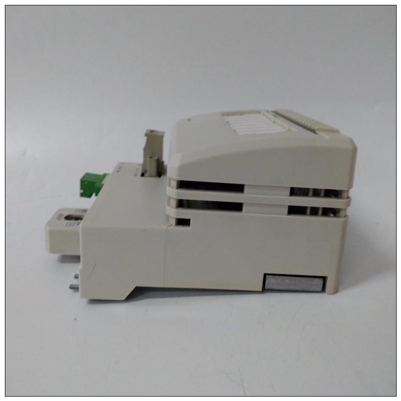
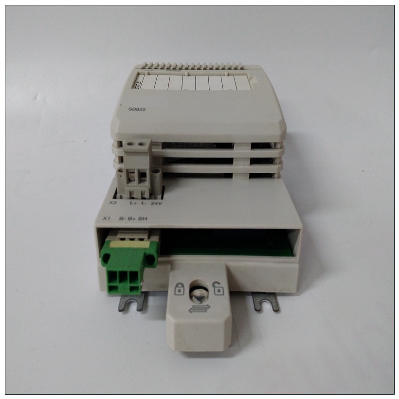
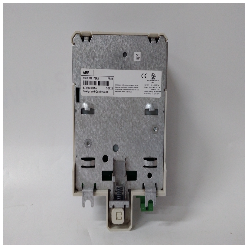
SB822逻辑模块,ABB产品外观
P2信号多路复用由于P2背板连接器中可用引脚的供应有限在为MVME761输入/输出模式配置的MVME2700机型中,某些信号通过VMEbus连接器P2多路传输,用于额外的输入/输出容量。
受影响的信号是在之间传递的同步输入/输出控制信号基板和MVME761过渡模块。多路复用是对软件完全透明的硬件功能。
")
SB822逻辑模块P2多路复用功能涉及四个信号:MXDO、MXDI、,MXCLK和MXSYNC∗.MXDO是来自主板和MXDI是来自MVME761模块的时间多路复用线路。MXCLK公司是用于MXDO和MXDI数据线的10 MHz位时钟。MXSYNC∗ 是在时隙15(参考下表)由MVME2700基板。MVME761转换模块使用MXSYNC∗ 与基本boardABORT开关(S1)同步中止开关位于LED夹层上。它可以由软件以及手工操作。当通过软件启用时,中止开关可以向处理器生成中断信号。中断正常用于中止程序执行并将控制返回给调试器固件位于MVME2700 EPROM和闪存中。这个中断信号通过ISA总线中断线到达处理器模块IRQ8∗. 该信号也可在Z8536 CIO设备的引脚PB7处获得,它处理各种状态信号、串行输入/输出线和计数器。连接到中止开关的断路器是一个边缘敏感电路,过滤以消除开关反弹。
复位开关(S2)复位开关位于LED夹层上。复位开关重置所有车载设备;它还驱动系统重置∗ 如果MVME2700是系统控制器。Universe II ASIC包括全局和局部复位驱动器。什么时候Universe II作为VMEbus系统控制器、复位驱动器运行通过断言VMEbus信号SYSRESET来提供全局系统重置∗.系统重置∗ 信号可能由复位开关产生,通电重置、看门狗超时或通过杂项控件中的控制位在Universe II ASIC中注册(MISC_CTL)。系统重置∗ 残余根据VMEbus规范的要求,至少断言200毫秒。类似地,Universe II ASIC提供输入信号和控制位启动本地重置操作。通过设置控制位,软件可以将电路板保持在重置状态,禁止故障电路板参与在正常系统操作中。即使在以下情况下,也会启用本地重置驱动程序Universe II ASIC不是系统控制器。本地重置可能是由重置开关、通电重置、看门狗超时、VMEbus系统重置∗, 或MISC\U CTL寄存器中的控制位。
P2 Signal Multiplexing
Due to the limited supply of available pins in the P2 backplane connectors
of MVME2700 models that are configured for MVME761 I/O mode,
certain signals are multiplexed through VMEbus connector P2 for
additional I/O capacity.
The signals affected are synchronous I/O control signals that pass between
the base board and the MVME761 transition module. The multiplexing is
a hardware function that is entirely transparent to software.
Four signals are involved in the P2 multiplexing function: MXDO, MXDI,
MXCLK, and MXSYNC∗.
MXDO is a time-multiplexed data output line from the main board and
MXDI is a time-multiplexed line from the MVME761 module. MXCLK
is a 10 MHz bit clock for the MXDO and MXDI data lines. MXSYNC∗ is
asserted for one bit time at time slot 15 (refer to the following table) by the
MVME2700 base board. The MVME761 transition module uses
MXSYNC∗ to synchronize with the base boardABORT Switch (S1)
The ABORT switch is located on the LED mezzanine. It can be actuated by
software as well as by hand. When enabled by software, the ABORT switch
can generate an interrupt signal to the processor. The interrupt is normally
used to abort program execution and return control to the debugger
firmware located in the MVME2700 EPROM and Flash memory. The
interrupt signal reaches the processor module via ISA bus interrupt line
IRQ8∗. The signal is also available at pin PB7 of the Z8536 CIO device,
which handles various status signals, serial I/O lines, and counters.The interrupter connected to the ABORT switch is an edge-sensitive circuit,
filtered to remove switch bounce.
RESET Switch (S2)
The RESET switch is located on the LED mezzanine. The RESET switch
resets all onboard devices; it also drives a SYSRESET∗ signal if the
MVME2700 is the system controller.
The Universe II ASIC includes both a global and a local reset driver. When
the Universe II operates as the VMEbus system controller, the reset driver
provides a global system reset by asserting the VMEbus signal SYSRESET∗.
A SYSRESET∗ signal may be generated by the RESET switch, a power-up
reset, a watchdog timeout, or by a control bit in the Miscellaneous Control
Register (MISC_CTL) in the Universe II ASIC. SYSRESET∗ remains
asserted for at least 200 ms, as required by the VMEbus specification.
Similarly, the Universe II ASIC supplies an input signal and a control bit
to initiate a local reset operation. By setting a control bit, software can
maintain a board in a reset state, disabling a faulty board from participating
in normal system operation. The local reset driver is enabled even when
the Universe II ASIC is not system controller. Local resets may be
generated by the RESET switch, a power-up reset, a watchdog timeout, a
VMEbus SYSRESET∗, or a control bit in the MISC_CTL register.

