


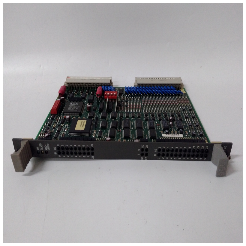
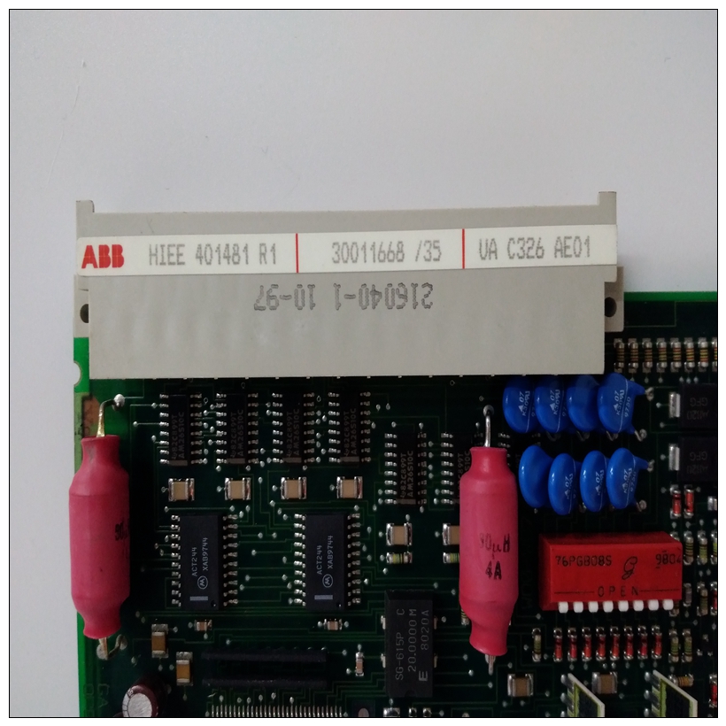
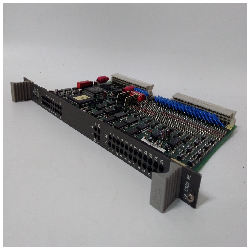
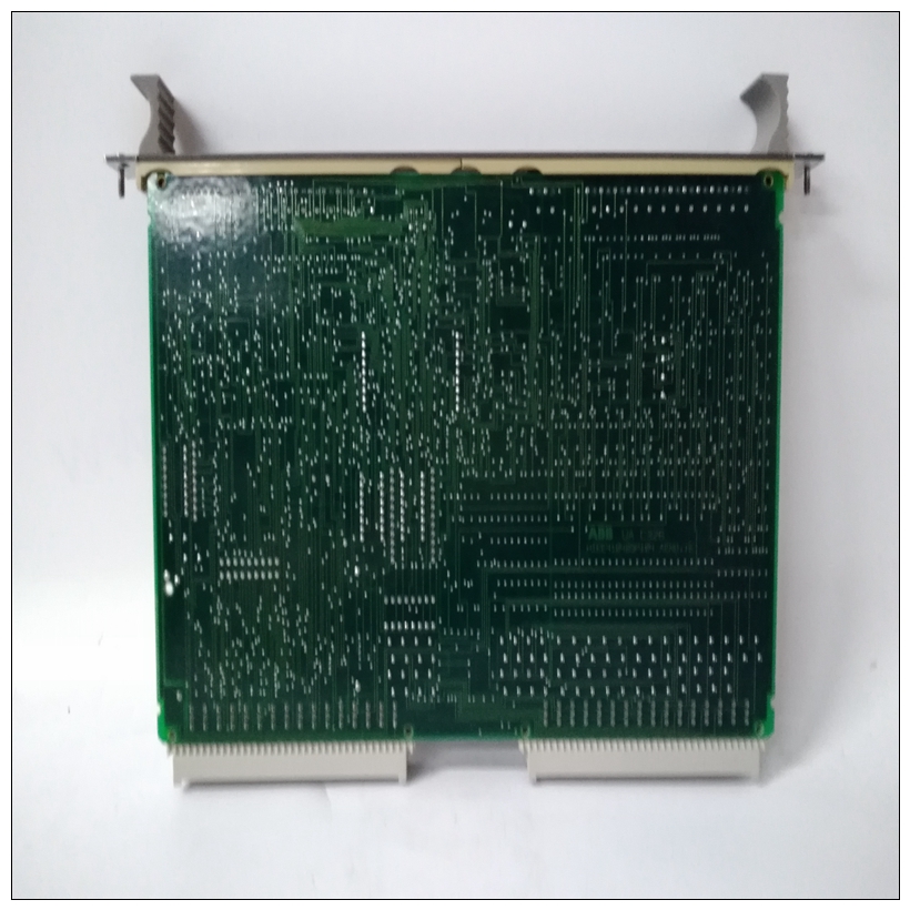
HIEE401481R1控制卡件,ABB使用配置教程
同步(SDLC/HDLC)和异步协议。硬件支持110B/s至38.4KB/s的异步串行波特率和同步波特率高达2.5MB/s。每个端口也支持CT、DCD、RTS和DTR控制信号作为TxD和RxD发送/接收数据信号和TxC/RxC同步时钟信号。因为并非所有调制解调器控制线都可用在Z85230中,使用Z8536 CIO设备提供缺失的调制解调器线EIA-232-D连接EIA-232-D标准定义了此串行接口。接口采用不平衡(单端)信号,通常与DB-25连接器一起使用,但其他连接器样式(例如,DB-9和RJ-45)有时用作好表B-1列出了标准EIA-232-D互连。
")
HIEE401481R1控制卡件并非所有引脚表中列出的是每种应用中都需要的。要正确解释信息,请记住EIA-232-D串行开发了将终端连接到调制解调器的接口。串行数据将发送设备留在传输数据(TxD)线上,并到达接收数据(RxD)线上的接收设备。计算时设备在没有调制解调器的情况下互连,其中一个单元必须配置为终端(数据终端设备:DTE),另一个配置为调制解调器(数据电路终端设备:DCE)。因为计算机是通常配置为与终端一起工作,称为配置在大多数情况下作为调制解调器。传输数据。待传输的数据;从终端输入调制解调器。3 RxD接收数据。从接收线解调的数据;输出自调制解调器到终端。
4发送RTS请求。当需要传输数据时,从终端输入调制解调器消息RTS关闭时,调制解调器载波保持关闭状态。当旋转RTS时打开时,调制解调器立即打开载波。
5 CT清除发送。从调制解调器到终端的输出,以指示该消息传输可以开始。当使用调制解调器时,电流互感器从关到开延时后RTS的转换。
6 DSR数据集就绪。从调制解调器到终端的输出,指示调制解调器已准备好发送或接收数据。
7 SG信号接地。调制解调器接口上所有信号的公共返回线。8 DCD数据载波检测。从调制解调器到终端的输出表明正在接收承运人。9-14未使用。
15 TxC传输时钟(DCE)。调制解调器到终端的输出;时钟数据来自将终端连接到调制解调器。16未使用。17 RxC接收时钟。从终端到调制解调器的输出;时钟从终端到调制解调器。18、19未使用。20 DTR数据终端就绪。从终端输入调制解调器;表明终端已准备好发送或接收数据。
synchronous (SDLC/HDLC) and asynchronous protocols. The hardware
supports asynchronous serial baud rates of 110B/s to 38.4KB/s and
synchronous baud rates of up to 2.5MB/s.
Each port supports the CTS, DCD, RTS, and DTR control signals, as well
as the TxD and RxD transmit/receive data signals and TxC/RxC
synchronous clock signals. Since not all modem control lines are available
in the Z85230, a Z8536 CIO device is used to provide the missing modem
lines.
EIA-232-D Connections
The EIA-232-D standard defines the electrical and mechanical aspects of
this serial interface. The interface employs unbalanced (single-ended)
signaling and is generally used with DB-25 connectors, although other
connector styles (for example, DB-9 and RJ-45) are sometimes used as
well.
Table B-1 lists the standard EIA-232-D interconnections. Not all pins
listed in the table are necessary in every application.
To interpret the information correctly, remember that the EIA-232-D serial
interface was developed to connect a terminal to a modem. Serial data
leaves the sending device on a Transmit Data (TxD) line and arrives at the
receiving device on a Receive Data (RxD) line. When computing
equipment is interconnected without modems, one of the units must be
configured as a terminal (data terminal equipment: DTE) and the other as
a modem (data circuit-terminating equipment: DCE). Since computers are
normally configured to work with terminals, they are said to be configured
as a modem in most cases.Transmit Data. Data to be transmitted; input to modem from terminal.
3 RxD Receive Data. Data which is demodulated from the receive line; output from
modem to terminal.
4 RTS Request To Send. Input to modem from terminal when required to transmit a
message. With RTS off, the modem carrier remains off. When RTS is turned
on, the modem immediately turns on the carrier.
5 CTS Clear To Send. Output from modem to terminal to indicate that message
transmission can begin. When a modem is used, CTS follows the off-to-on
transition of RTS after a time delay.
6 DSR Data Set Ready. Output from modem to terminal to indicate that the modem
is ready to send or receive data.
7 SG Signal Ground. Common return line for all signals at the modem interface.
8 DCD Data Carrier Detect. Output from modem to terminal to indicate that a valid
carrier is being received.
9-14 Not used.
15 TxC Transmit Clock (DCE). Output from modem to terminal; clocks data from
the terminal to the modem.
16 Not used.
17 RxC Receive Clock. Output from terminal to modem; clocks input data from the
terminal to the modem.
18, 19 Not used.
20 DTR Data Terminal Ready. Input to modem from terminal; indicates that the
terminal is ready to send or receive data.

