


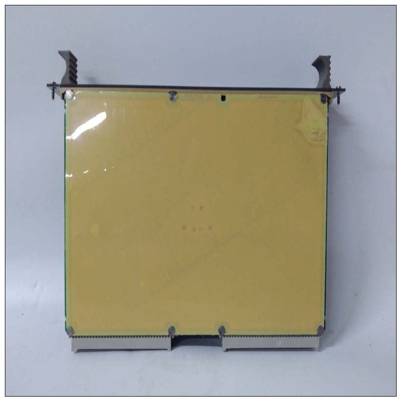
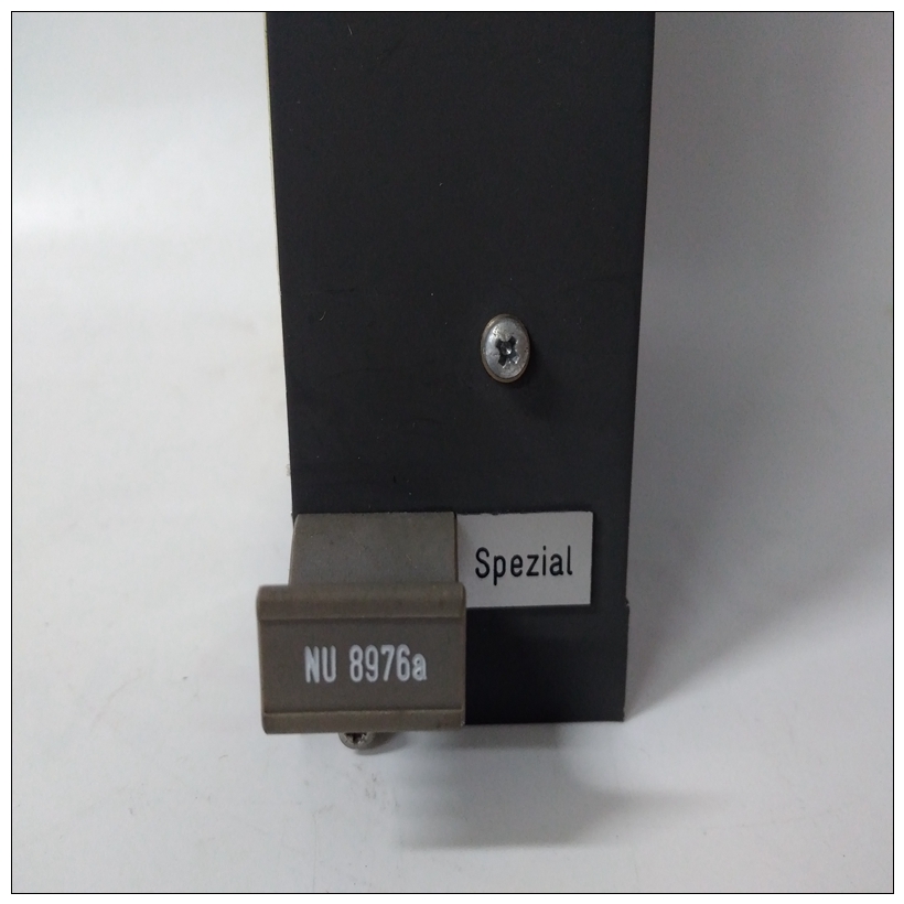
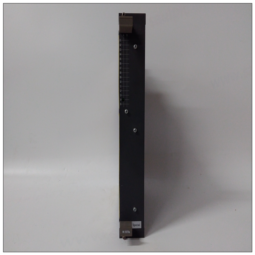
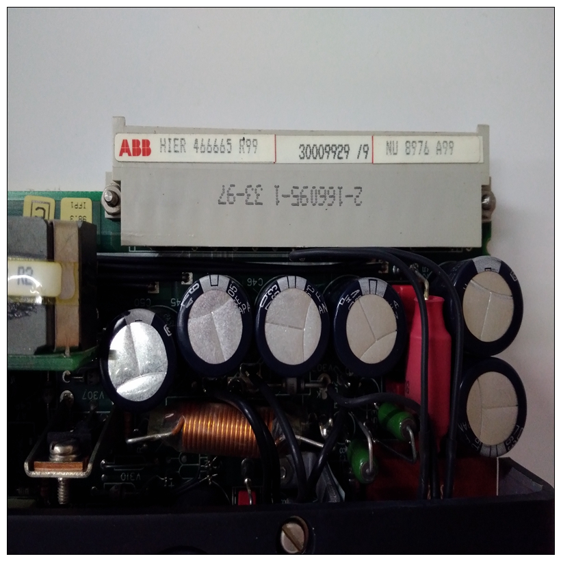
NU8976a数字量模块,ABB用户手册
通用连接器下表描述了使用相同引脚的连接器MVME712M以及MVME761兼容版本的分配基板的。LED夹层接头J114针连接器(基板上的J1)提供基板和LED夹层模块。在基板上连接器是一个2x7头。在LED夹层上,它是一个2x7表面安装插座条。卸下LED夹层可以使用夹层连接器用作远程状态和控制连接器。
")
NU8976a数字量模块在此应用中,J1可连接至用户提供的外部电缆,以承载重置和将中止信号和LED线路连接到远离控制面板的控制面板MVME2603/2604。最大电缆长度为15英尺。引脚分配如下所示:调试连接器J2190针连接器(MVME2603/2604基板上的J2)提供访问处理器总线(MPU总线)和一些网桥/内存控制器信号。它可以用于调试目的。引脚分配为下表中列出了一个50针高密度连接器(基板上的J4)提供基板和可选外部软盘之间的接口驾驶除了磁盘驱动器控制信号外,还需要一组16条线路可用于驱动外部LED阵列。管脚分配在中列出下表。PCI扩展连接器J5MVME2603/2604具有堆叠PMC承载板的功能用于额外PCI扩展的基板。114针接头(J5开基板)提供MVME2603/2604和承载板。下表列出了端号分配。键盘和鼠标连接器J6、J8MVME2603/2604有两个6针圆形DIN连接器,位于键盘(J6)和鼠标(J8)的前面板。引脚分配以下两个表中列出了这些连接器。DRAM夹层连接器J7190针连接器(MVME2603/2604基板上的J7)为处理器总线(MPU总线)和RAM200 DRAM之间的接口阁楼。下表列出了端号分配。PCI夹层卡连接器四个64针连接器(MVME2603/2604上的J11/12/13/14)供电基板和可选PCI夹层卡之间的接口(PMC)。引脚分配如表4-8所示。
Common Connectors
The following tables describe connectors used with the same pin
assignments by MVME712M, as well as MVME761-compatible versions
of the base board.
LED Mezzanine Connector J1
A 14-pin connector (J1 on the base board) supplies the interface between
the base board and the LED mezzanine module. On the base board, this
connector is a 2x7 header. On the LED mezzanine, it is a 2x7 surfacemount socket strip.
Removing the LED mezzanine makes the mezzanine connector available
for service as a remote status and control connector. In this application, J1
can be connected to a user-supplied external cable to carry the Reset and
Abort signals and the LED lines to a control panel located apart from the
MVME2603/2604. Maximum cable length is 15 feet. The pin assignments
are as follows:Debug Connector J2
A 190-pin connector (J2 on the MVME2603/2604 base board) provides
access to the processor bus (MPU bus) and some bridge/memory controller
signals. It can be used for debugging purposes. The pin assignments are
listed in the following tableA 50-pin high-density connector (J4 on the base board) supplies the
interface between the base board and an optional external floppy disk
drive. In addition to the disk drive control signals, a set of 16 lines is
available to drive an external LED array. The pin assignments are listed in
the following table.PCI Expansion Connector J5
The MVME2603/2604 has provision for stacking a PMC carrier board on
the base board for additional PCI expansion. A 114-pin connector (J5 on
the base board) supplies the interface between the MVME2603/2604 and
the carrier board. The pin assignments are listed in the following table.Keyboard and Mouse Connectors J6, J8
The MVME2603/2604 has two 6-pin circular DIN connectors located on
the front panel for the keyboard (J6) and mouse (J8). The pin assignments
for those connectors are listed in the following two tables.DRAM Mezzanine Connector J7
A 190-pin connector (J7 on the MVME2603/2604 base board) supplies the
interface between the processor bus (MPU bus) and the RAM200 DRAM
mezzanine. The pin assignments are listed in the following table.PCI Mezzanine Card Connectors
Four 64-pin connectors (J11/12/13/14 on the MVME2603/2604) supply
the interface between the base board and an optional PCI mezzanine card
(PMC). The pin assignments are listed in Table 4-8.

