


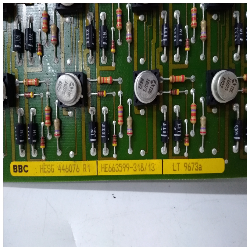
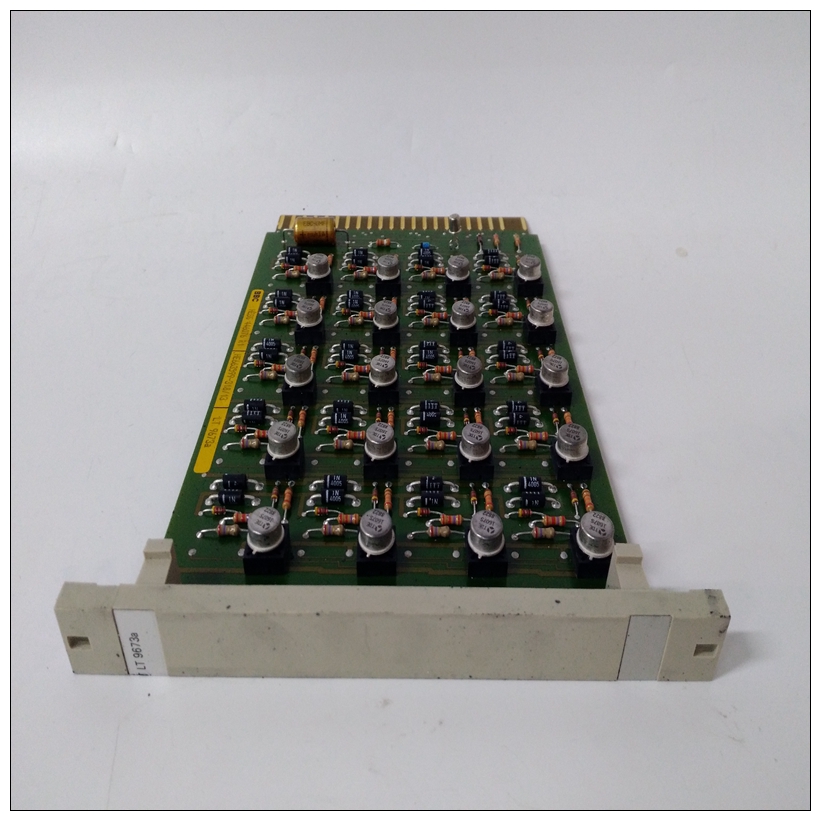
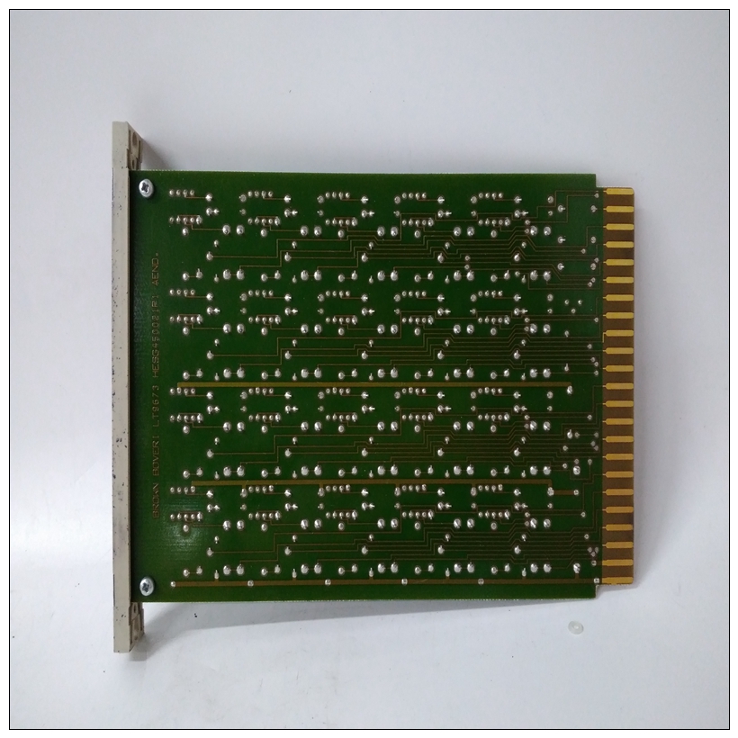
HE663599-31813模块卡件,LT9673a使用方法教程
❏ 由+5V直流电源开发的熔断SCSI终端电源接头P2处
❏ 一个64针DIN连接器,用于连接EIA-232-D、并行、SCSI、,和以太网信号传输至MVME712MMVME761过渡模块MVME761过渡模块(第1-26页图1-12)和P2适配器板与MVME2603/2604底座一起使用板
MVME761的功能包括:
❏ 并行打印机端口(符合IEEE 1284-I)
❏ 支持10BaseT/100BaseTX连接的以太网接口
")
HE663599-31813模块卡件❏ 两个EIA-232-D异步串行端口(标识为COM1和前面板上的COM2)
❏ 两个同步串行端口(前端的串行3和串行4面板),可配置EIA-232-D、EIA-530、V.35或X.21协议❏ 两个60针串行接口模块(SIM)连接器串行接口模块MVME761上的同步串行端口可通过串行端口配置接口模块(SIM),与适当的跳线一起使用过渡模块和基板上的设置。SIM是小型插件印刷电路板,包含将TTL电平端口转换为各种工业标准串行接口(如EIA-232、EIA-530等)所需的标准电压电平所需的所有电路。SIM是可用于以下配置:本章总结了以下几组的引脚分配:MVME2603/2604的互连信号:
❏ 具有MVME712M通用引脚分配的连接器作为MVME761兼容版本的基板❏ 具有特定于MVME761的引脚分配的连接器-基板的兼容版本下表仅提供管脚分配。有关详细信息有关各种互连信号的说明,请咨询支持部门MVME2603/2604 single的信息文档包板机或过渡的支持信息部分必要的模块文档
Fused SCSI terminator power developed from the +5V DC present
at connector P2
❏ A 64-pin DIN connector to interface the EIA-232-D, parallel, SCSI,
and Ethernet signals to the MVME712M
MVME761 Transition Module
The MVME761 transition module (Figure 1-12 on page 1-26) and P2
adapter board are used in conjunction with the MVME2603/2604 base
board.
The features of the MVME761 include:
❏ A parallel printer port (IEEE 1284-I compliant)
❏ An Ethernet interface supporting 10BaseT/100BaseTX connections
❏ Two EIA-232-D asynchronous serial ports (identified as COM1 and
COM2 on the front panel)
❏ Two synchronous serial ports (SERIAL 3 and SERIAL 4 on the front
panel), configurable for EIA-232-D, EIA-530, V.35, or X.21
protocols
❏ Two 60-pin Serial Interface Module (SIM) connectors
Serial Interface Modules
The synchronous serial ports on the MVME761 are configurable via serial
interface modules (SIMs), used in conjunction with the appropriate jumper
settings on the transition module and base board. The SIMs are small plugin printed circuit boards which contain all the circuitry needed to convert TTL-level port to the standard voltage levels needed by various industrystandard serial interfaces, such as EIA-232, EIA-530, etc. SIMs are
available for the following configurations:This chapter summarizes the pin assignments for the following groups of
interconnect signals for the MVME2603/2604:
❏ Connectors with pin assignments common to MVME712M, as well
as MVME761-compatible versions of the base board❏ Connectors with pin assignments specific to MVME761-
compatible versions of the base board
The following tables furnish pin assignments only. For detailed
descriptions of the various interconnect signals, consult the support
information documentation package for the MVME2603/2604 single
board computer or the support information sections of the transition
module documentation as necessary

