


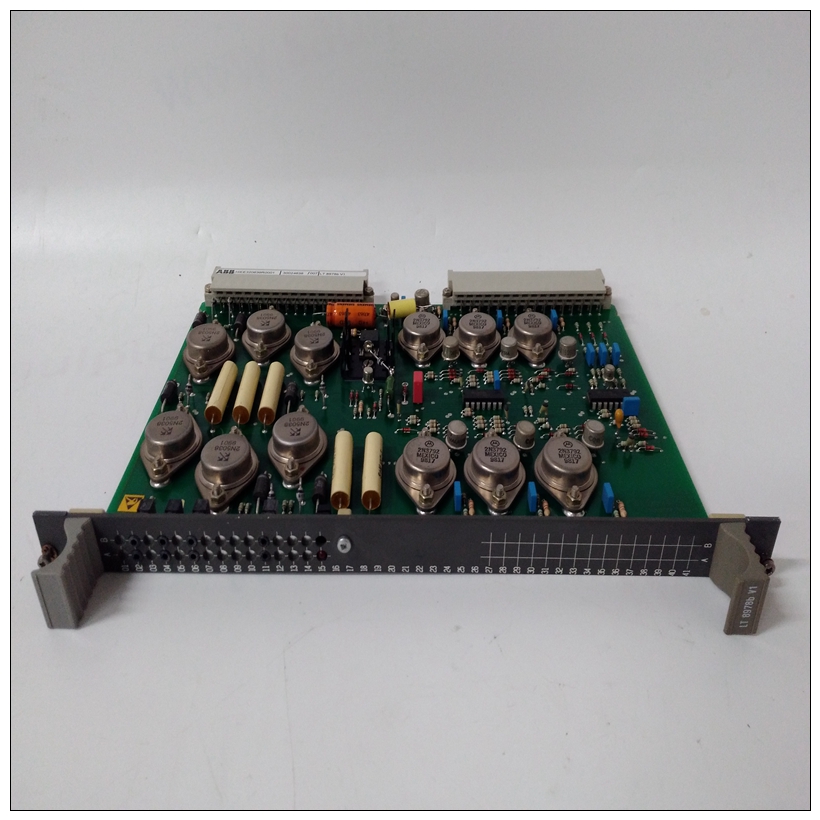
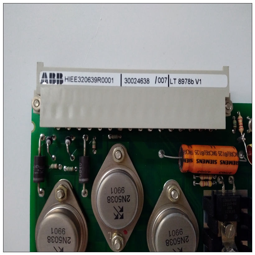
HIEE320639R0001工控卡件,ABB中文使用说明
多功能开关(可复位保险丝)MVME2603/2604基板使用带保险丝的+5V DC、+12V DC和–来自VMEbus背板的12V直流电源,通过连接器P1和P2.3 V DC和核心处理器电压电源由车载+5Vdc。下表列出了保险丝及其电压保护输入/输出功率
MVME2603/2604基板提供+12V DC和(在MVME761中输入/输出模式)–通过多功能开关向过渡模块提供12V直流电源(可复位保险丝)R34和R28。
")
HIEE320639R0001工控卡件这些电压源提供电源串行端口驱动程序和连接到转换的任何LAN收发器单元保险丝+5V直流电源提供给基板的键盘和鼠标连接器通过多路开关R30和14针组合LED夹层/远程重置接头J1。上的FUS LED(DS5)MVME2603/2604前面板在所有三个电压均为可获得的在MVME712M输入/输出模式下,MVME712M上的黄色DS1 LED也发出+12V直流LAN电源可用性的信号,反过来表明多路开关R34良好。如果以太网收发器无法工作,请检查多路开关R34。
在MVME712M输入/输出模式下,MVME2603/2604提供SCSI终端通过P2适配器板上的1A保险丝(F1)供电。如果保险丝熔断,SCSI设备可能会工作不稳定或无法正常工作全部的P2适配器板连接至转换模块,并带有SCSI总线连接到转换模块,当SCSI终端电源可用时,模块上的绿色SCSI指示灯点亮。如果SCSISCSI总线操作期间,转换模块上的LED闪烁,请检查P2适配器板上的保险丝F1。注意,因为SCSI总线上的任何设备都可以提供TERMPWR,并且由于FUS LED监控多个电压的状态,因此LED不直接指示任何单个保险丝的状况。如果LED闪烁或熄灭,请检查所有保险丝(多开关)。在MVME761输入/输出模式下,MVME2603/2604提供SCSI终端通过P2适配器上的多开关(可复位保险丝)供电板
Polyswitches (Resettable Fuses)
The MVME2603/2604 base board draws fused +5V DC, +12V DC, and
–12V DC power from the VMEbus backplane through connectors P1 and
P2. The 3.3V DC and the core processor voltage power is supplied by the
on-board +5Vdc. The following table lists the fuses with the voltages they
protect.I/O Power
The MVME2603/2604 base board furnishes +12V DC and (in MVME761
I/O mode) –12V DC power to the transition module through polyswitches
(resettable fuses) R34 and R28 respectively. These voltage sources power
the serial port drivers and any LAN transceivers connected to the transition
module. Fused +5V DC power is supplied to the base board’s keyboard
and mouse connectors through polyswitch R30 and to the 14-pin combined
LED-mezzanine/remote-reset connector, J1. The FUS LED (DS5) on the
MVME2603/2604 front panel illuminates when all three voltages are
available.
In MVME712M I/O mode, the yellow DS1 LED on the MVME712M also
signals the availability of +12V DC LAN power, indicating in turn that
polyswitch R34 is good. If the Ethernet transceiver fails to operate, check
polyswitch R34.
In MVME712M I/O mode, the MVME2603/2604 supplies SCSI
terminator power through a 1A fuse (F1) located on the P2 adapter board.
If the fuse is blown, the SCSI device(s) may function erratically or not at
all. With the P2 adapter board cabled to a transition module and with an
SCSI bus connected to the transition module, the green SCSI LED on the module illuminates when SCSI terminator power is available. If the SCSI
LED on the transition module flickers during SCSI bus operation, check
fuse F1 on the P2 adapter board.Note Because any device on the SCSI bus can provide TERMPWR, and
because the FUS LED monitors the status of several voltages, the
LED does not directly indicate the condition of any single fuse.
If the LED flickers or goes out, check all the fuses
(polyswitches).
In MVME761 I/O mode, the MVME2603/2604 supplies SCSI terminator
power through a polyswitch (resettable fuse) located on the P2 adapter
board.

