


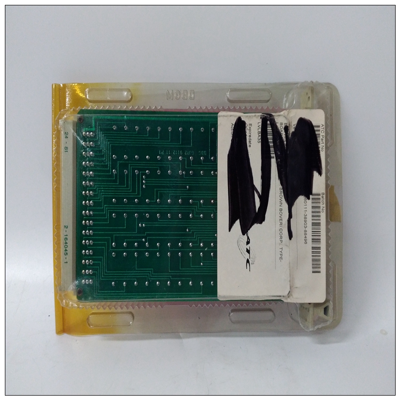
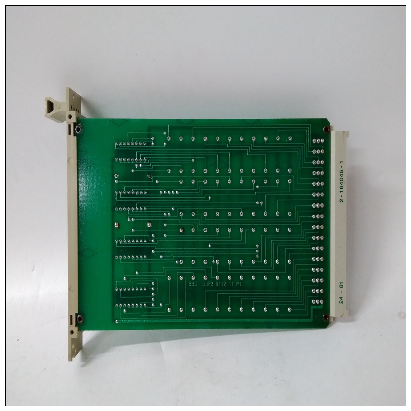
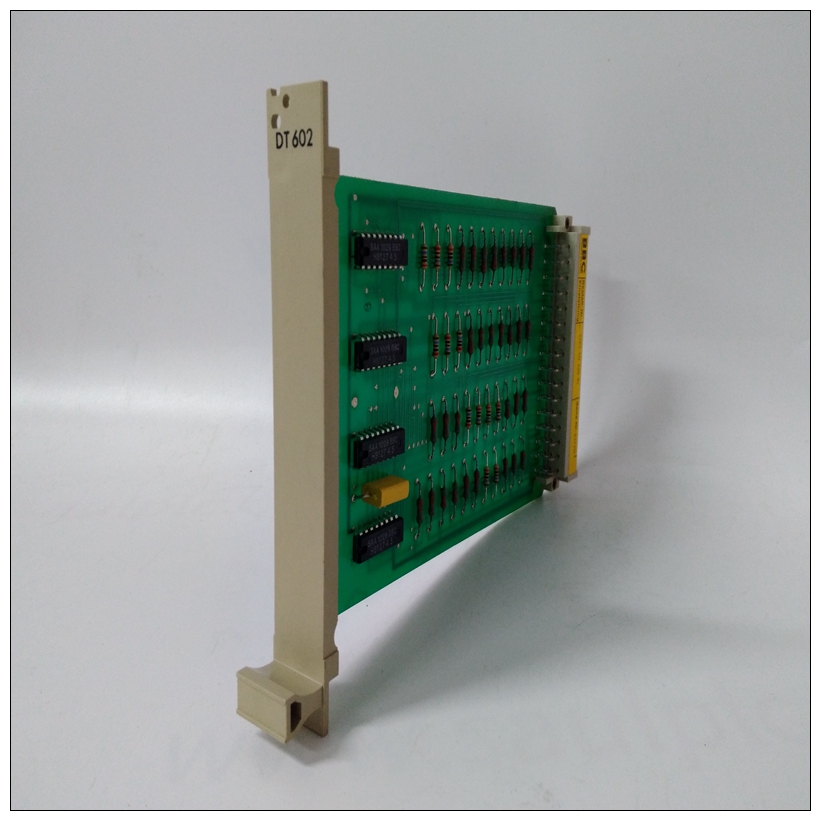
GJR2911200R1转速计卡件,ABB产品外观
SCSI终止配置系统的个人必须确保SCSI总线两端正确终止。
在MVME712M输入/输出模式下,MVME2603/2604基板使用为使用的P2适配器板上的SCSI总线终端提供的插座使用MVME712M。如果SCSI总线终止于适配器板,终端电阻器必须安装在那里+SCSI的5V直流电源总线终端PWR信号和终端电阻器通过保险丝供电位于适配器板上。
")
GJR2911200R1转速计卡件在MVME761输入/输出模式下,与MVME761一起使用的P2适配器板具有用于启用/禁用SCSI总线终端的跳线+5V直流电源SCSI终端通过适配器上的多开关提供板以太网接口
MVME2603/2604 VME模块使用数字设备的DEC芯片21140 PCI快速以太网LAN控制器,用于实现以太网支持AUI(通过MVME712M)和10BaseT/100BaseTX(通过MVME761)连接。平衡的差分收发器线路通过车载变压器耦合。
MVME2603/2604路由其AUI和10BaseT/100BaseTX线路通过P2连接器连接到过渡模块(如图所示第1-47页图1-21和第1-49页图1-22)。MVME712M前部面板具有用于AUI连接的行业标准DB-15连接器。MVME761支持10BaseT/100BaseTX连接。每个MVME2603/2604分配一个以太网站地址。这个地址是$08003E2xxxxx,其中xxxxx是唯一的5位数字分配给电路板(即每个电路板的xxxxx值不同)。每个MVME2603/2604在标签上显示其以太网站地址连接到PMC连接器禁止区域的基板上前面板。此外,包括以太网站的六个字节地址存储在片外以太网控制器的SROM中即,值08003E2xxxxx存储在SROM中。在1F2C美元的补偿下可以读取前四个字节(08003E2x)。在1F30美元的补偿下,较低的可以读取两个字节(xxxx)。MVME2603/2604调试器,能够通过CNFG命令。
注:唯一以太网地址在工厂设置,不应被改变。任何更改此地址的尝试都可能创建节点或总线争用,从而使电路板无法运行。如果SROM中的数据丢失,请使用PMC中标签上的数字连接器禁止区域恢复。对于过渡模块AUI或10BaseT/100BaseTX连接器,有关详细信息,请参阅用户手册MVME712M或MVME761(在附录D中列出,相关文件)。参考BBRAM/TOD时钟存储器
SCSI Termination
The individual configuring the system must ensure that the SCSI bus is
properly terminated at both ends.
In MVME712M I/O mode, the MVME2603/2604 base board uses the
sockets provided for SCSI bus terminators on the P2 adapter board used
with the MVME712M. If the SCSI bus ends at the adapter board,
termination resistors must be installed there. +5V DC power to the SCSI
bus TERMPWR signal and termination resistors is supplied through a fuse
located on the adapter board.
In MVME761 I/O mode, the P2 adapter board used with the MVME761
has a jumper to enable/disable SCSI bus terminators. +5V DC power for
SCSI termination is supplied through a polyswitch located on the adapter
board.Ethernet Interface
The MVME2603/2604 VME module uses Digital Equipment’s DECchip
21140 PCI Fast Ethernet LAN controller to implement an Ethernet
interface that supports both AUI (via MVME712M) and
10BaseT/100BaseTX (via MVME761) connections. The balanced
differential transceiver lines are coupled via on-board transformers.
The MVME2603/2604 routes its AUI and 10BaseT/100BaseTX lines
through the P2 connector to the transition module (as illustrated in Figure
1-21 on page 1-47 and Figure 1-22 on page 1-49). The MVME712M front
panel has an industry-standard DB-15 connector for an AUI connection.
The MVME761 supports 10BaseT/100BaseTX connections.
Every MVME2603/2604 is assigned an Ethernet station address. The
address is $08003E2xxxxx, where xxxxx is the unique 5-nibble number
assigned to the board (that is, every board has a different value for xxxxx).
Each MVME2603/2604 displays its Ethernet station address on a label
attached to the base board in the PMC connector keepout area just behind
the front panel. In addition, the six bytes including the Ethernet station
address are stored in an SROM off the DECchip Ethernet controller, that
is, the value 08003E2xxxxx is stored in SROM. At an offset of $1F2C, the
upper four bytes (08003E2x) can be read. At an offset of $1F30, the lower
two bytes (xxxx) can be read. The MVME2603/2604 debugger, PPCBug,
has the capability to retrieve or set the Ethernet station address via the
CNFG command.
Note The unique Ethernet address is set at the factory and should not
be changed. Any attempt to change this address may create node
or bus contention and thereby render the board inoperable.
If the data in SROM is lost, use the number on the label in the PMC
connector keepout area to restore it.
For the pin assignments of the transition module AUI or
10BaseT/100BaseTX connector, refer to the user’s manual for the
MVME712M or MVME761 (listed in Appendix D, Related
Documentation) respectively. Refer to the BBRAM/TOD Clock memory

