


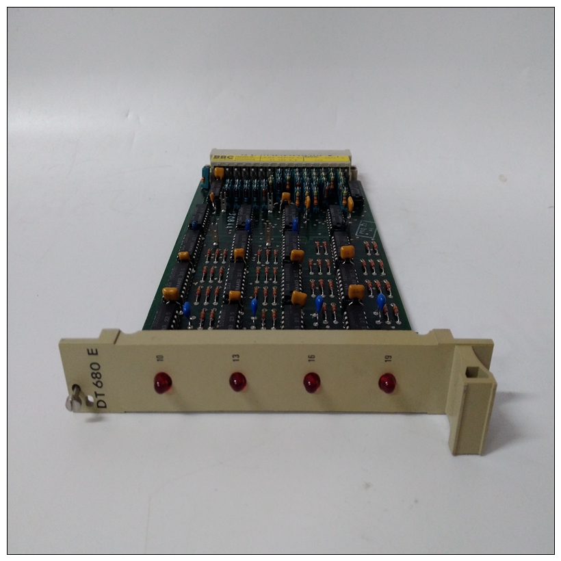
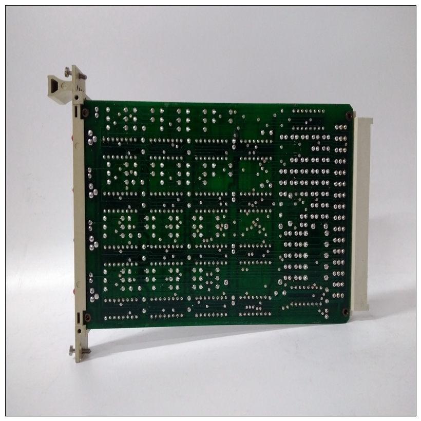
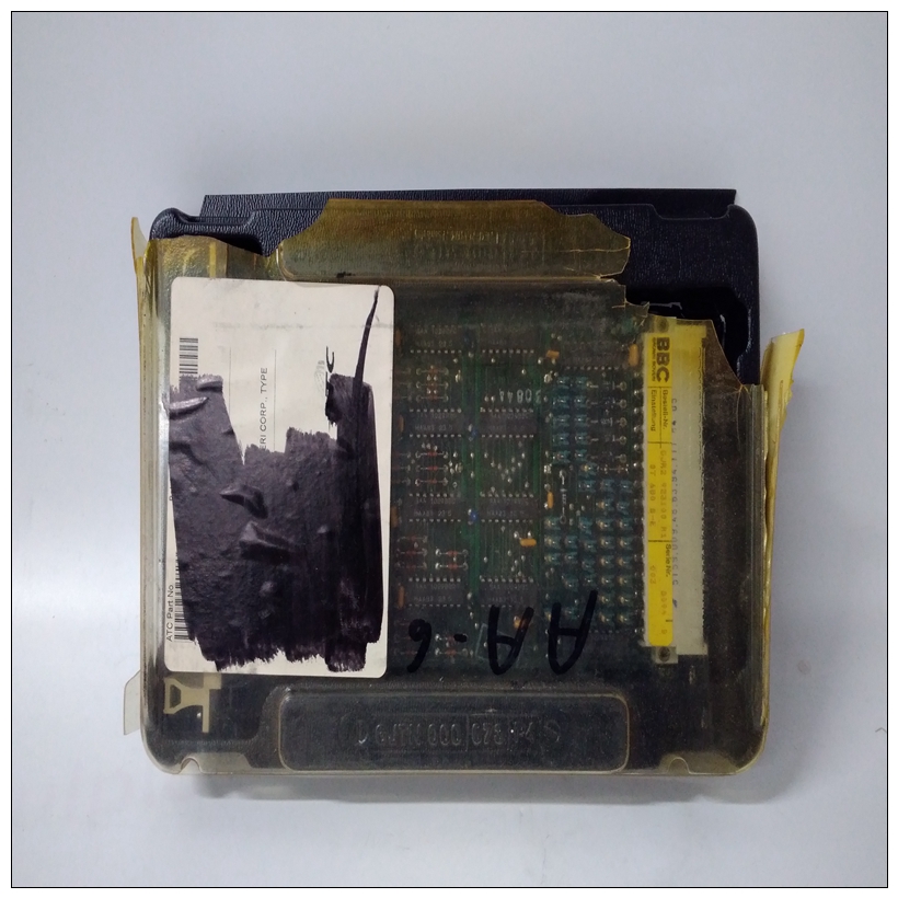
GJR2923100R1工控卡件,ABB使用速度
通电后,调试端口的波特率可以通过以下方式重新配置:使用197Bug调试器的端口格式(PF)命令。注:为了实现之间的高波特率串行通信197Bug和终端要工作,终端必须做一些握手的形式。如果正在使用的终端没有通过CTS线路进行硬件握手,然后必须进行XON/XOFF握手。如果用户收到乱码消息和缺少字符,则用户应检查确保XON/XOFF握手已启用的终端。
")
GJR2923100R1工控卡件4.如果需要连接设备(如主机系统和/或串行打印机)连接到其他EIA-232-D端口连接器(标记为串行MVME712X转换模块上的端口2、3和4),连接如上文步骤3所述,安装适当的电缆并配置端口。通电后,可以通过编程重新配置这些端口MVME197LE CD2401串行控制器芯片(SCC),或使用197Bug PF命令。注意,MVME197LE还包含一个并行端口。使用平行线带有MVME197LE的设备(如打印机)将其连接到“打印机”通过MVME712X转换模块在P2处的端口。请参阅MVME197LE、MVME197DP和MVME197SP单板计算机一些可能的连接图的程序员参考指南。然而,您也可以使用诸如MVME335之类的模块来进行并行处理端口连接。
5、接通系统电源。197Bug执行一些自检并显示调试器提示“197 Bug>”(如果197Bug处于Board模式)。然而,如果ENV命令将197Bug置于系统模式,系统执行自检并尝试自动启动。请参阅ENV和MENU命令。它们列于表4-1中。如果置信度测试失败,则在出现第一个故障时中止测试遇到。如果可能,将显示适当的消息,并控制然后返回菜单。自动脚印Autoboot是包含在197Bug中的一个软件例程,用于提供引导操作系统的独立机制。这个autoboot例程按指定顺序自动扫描控制器和设备直到找到包含引导介质的有效可引导设备或列表筋疲力尽的如果找到有效的可引导设备,则会从该设备启动起动。控制器扫描顺序从最低的控制器开始检测到的逻辑单元号(LUN)为检测到的最高LUN。(参见附录B中的默认LUN)。通电时,Autoboot启用,并提供驱动器和控制器遇到的数字有效,将在系统控制台:
After power-up, the baud rate of the debug port can be reconfigured by
using the Port Format (PF) command of the 197Bug debugger.
Note In order for high-baud rate serial communication between
197Bug and the terminal to work, the terminal must do some
form of handshaking. If the terminal being used does not
do hardware handshaking via the CTS line, then it must do
XON/XOFF handshaking. If the user gets garbled messages
and missing characters, then the user should check the
terminal to make sure XON/XOFF handshaking is enabled.
4. If it is desired to connect devices (such as a host computer system and/or
a serial printer) to the other EIA-232-D port connectors (marked SERIAL
PORTS 2, 3, and 4 on the MVME712X transition module), connect the
appropriate cables and configure the port(s) as detailed in step 3 above.
After power-up, this(these) port(s) can be reconfigured by programming
the MVME197LE CD2401 Serial Controller Chip (SCC), or by using the
197Bug PF command.Note that the MVME197LE also contains a parallel port. To use a parallel
device, such as a printer, with the MVME197LE, connect it to the “printer”
port at P2 through an MVME712X transition module. Refer to the
MVME197LE, MVME197DP, and MVME197SP Single Board Computers
Programmer’s Reference Guide for some possible connection diagrams.
However, you could also use a module such as the MVME335 for a parallel
port connection.
5. Power up the system. 197Bug executes some self-checks and displays the
debugger prompt “197-Bug>” (if 197Bug is in Board Mode). However, if
the ENV command has put 197Bug in System Mode, the system performs
a self test and tries to autoboot. Refer to the ENV and MENU commands.
They are listed in Table 4-1.
If the confidence test fails, the test is aborted when the first fault is
encountered. If possible, an appropriate message is displayed, and control
then returns to the menu.Autoboot
Autoboot is a software routine that is contained in the 197Bug to provide an
independent mechanism for booting an operating system. This autoboot
routine automatically scans for controllers and devices in a specified sequence
until a valid bootable device containing a boot media is found or the list is
exhausted. If a valid bootable device is found, a boot from that device is
started. The controller scanning sequence goes from the lowest controller
Logical Unit Number (LUN) detected to the highest LUN detected. (Refer to
Appendix B for default LUNs).
At power-up, Autoboot is enabled, and providing the drive and controller

