


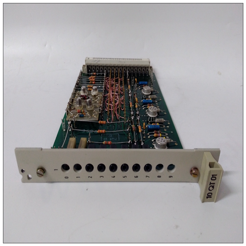
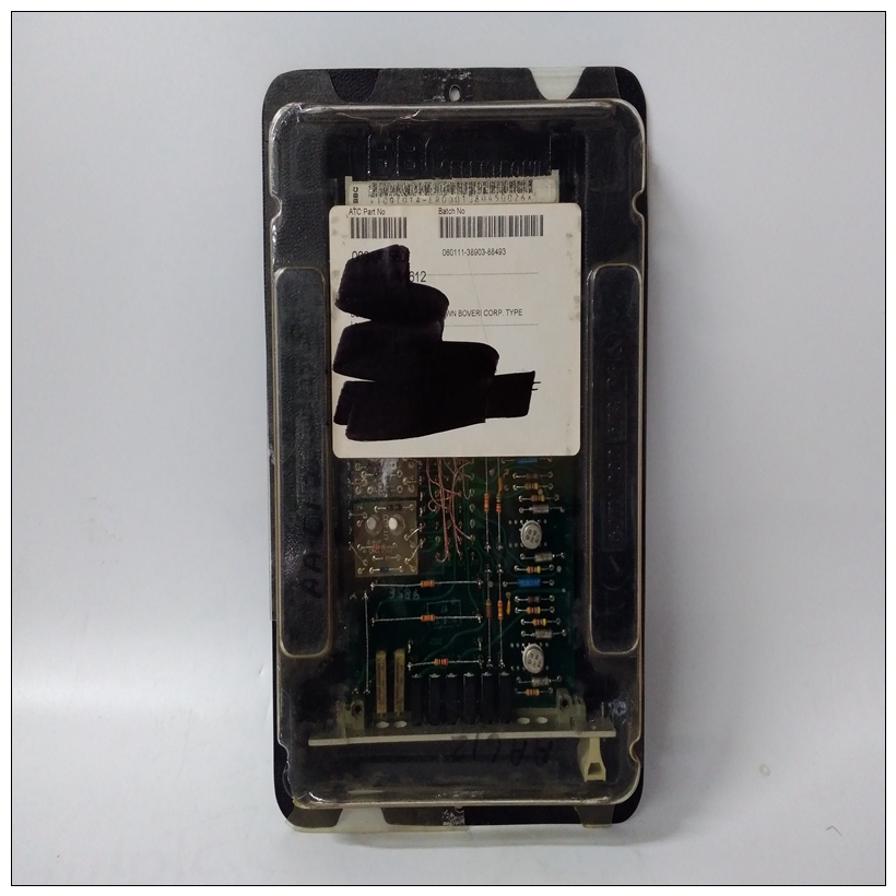
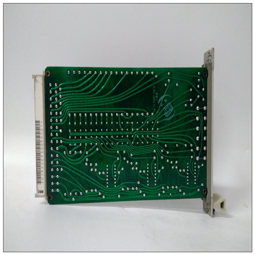
GJR2209300R0001卡件,ABB使用配置教程
特征这些是MVME197LE单板的一些主要功能计算机:
❏ MC88110 RISC微处理器❏ 32或64兆字节的64位动态随机存取存储器(DRAM)带纠错功能
❏ 1兆字节的闪存❏ 六个状态指示灯(故障、运行、SCON、LAN、SCSI和VME)
❏ 8KB的静态随机存取存储器(SRAM)和时间带电池备用RAM(BBRAM)的(TOD)时钟
❏ 两个按钮开关(中止和重置)❏ 128 KB的启动ROM
❏ 六个用于周期性中断的32位滴答计时器❏ 看门狗定时器
")
GJR2209300R0001卡件❏ 八次软件中断❏ 输入/输出
–具有直接内存访问(DMA)的SCSI总线接口–四个带EIA-232-D缓冲器的串行端口
–Centronics打印机端口–以太网收发器接口
❏ VMEbus接口–VMEbus系统控制器功能
–VMEbus与本地外围总线的接口(A24/A32、D8/D16/D32BLT(D8/D16/D32/D64))(BLT=块传输)–本地外围总线至VMEbus接口(A24/A32、D8/D16/D32BLT(D16/D32/D64))–VMEbus中断功能描述以下各节包含上主要模块的功能描述MVME197LE单板计算机。前面板开关和指示灯面板上有两个按钮开关和六个LEDMVME197LE模块。开关复位并中止。重置如果出现以下情况,开关(S3)将重置所有车载设备并驱动SYSRESET*信号:板是系统控制器。重置开关(S3)将重置所有车载设备如果电路板不是系统控制器,则为DCAM和ECDM以外的设备。VMEchip2生成SYSREST*信号。总线开关结合了本地重置和重置开关,以生成本地板重置。参考重置MVME197LE、MVME197DP和MVME197SP单板计算机程序员参考指南
Features
These are some of the major features of the MVME197LE single board
computer:
❏ MC88110 RISC Microprocessor
❏ 32 or 64 megabytes of 64-bit Dynamic Random Access Memory (DRAM)
with error correction
❏ 1 megabyte of Flash memory
❏ Six status LEDs (FAIL, RUN, SCON, LAN, SCSI, and VME)
❏ 8 kilobytes of Static Random Access Memory (SRAM) and Time of Day
(TOD) clock with Battery Backup RAM (BBRAM)
❏ Two push-button switches (ABORT and RESET)
❏ 128 kilobytes of BOOT ROM
❏ Six 32-bit tick timers for periodic interrupts
❏ Watchdog timer
❏ Eight software interrupts
❏ I/O
– SCSI Bus interface with Direct Memory Access (DMA)
– Four serial ports with EIA-232-D buffers
– Centronics printer port
– Ethernet transceiver interface
❏ VMEbus interface
– VMEbus system controller functions
– VMEbus interface to local peripheral bus (A24/A32, D8/D16/D32
BLT (D8/D16/D32/D64))(BLT = Block Transfer)
– Local peripheral bus to VMEbus interface (A24/A32, D8/D16/D32
BLT (D16/D32/D64))
– VMEbus interrupterFunctional Description
The following sections contain a functional description of the major blocks on
the MVME197LE single board computer.
Front Panel Switches and Indicators
There are two push-button switches and six LEDs on the front panel of the
MVME197LE module. The switches are RESET and ABORT. The RESET
switch (S3) will reset all onboard devices and drive the SYSRESET* signal if the
board is the system controller. The RESET switch (S3) will reset all onboard
devices except the DCAM and ECDM if the board is not the system controller.
The VMEchip2 generates the SYSREST* signal. The BusSwitch combines the
local reset and the reset switch to generate a local board reset. Refer to the Reset
Driver section in the VMEchip2 chapter of the MVME197LE, MVME197DP, and
MVME197SP Single Board Computers Programmer’s Reference Guide for more
information

