


GE 193X532ACG01现场控制板 PDF资料
1.产 品 资 料 介 绍:
中文资料:
GE 193X532ACG01 现场控制板简介
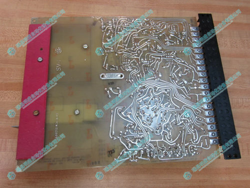
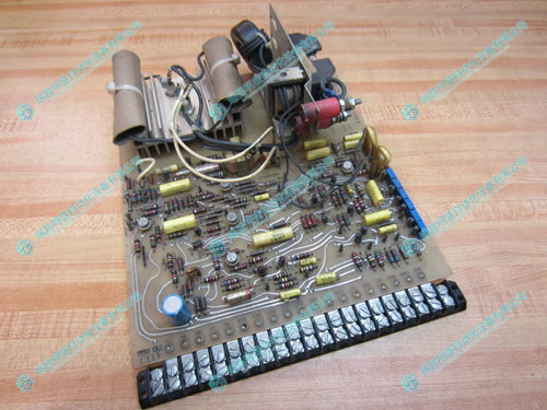
GE 193X532ACG01 是通用电气(General Electric)公司生产的 193X 系列工业控制板之一,广泛应用于早期的 GE 驱动控制系统中。它是一块插拔式现场控制板,常见于各种重工业环境中的直流电机或交流电机控制系统中,用于信号处理和逻辑控制。
技术规格与功能
控制类型:模拟与数字信号混合控制
安装方式:插卡式安装,通过金手指连接到系统母板
电源要求:通常为 ±15V DC,需与系统电源匹配
信号输入:电压、电流、继电器触点信号等
信号输出:控制驱动信号、模拟控制量、开关量输出
组件特性:含多组可调电位器(用于增益、偏移调整)
电路结构:由分立元件、运算放大器、滤波器等构成
状态指示:部分版本带有 LED 状态指示灯(用于调试或报警)
典型应用领域
GE Mark 系列驱动系统(如 Mark I、Mark II、Mark IV)
冶金、电解、电厂励磁控制系统
工业直流/交流电机调速系统
老旧工业设备自动化改造与维修支持
使用注意事项
安装前应确认系统是否断电,避免插拔时引起电弧或短路。
安装或维护过程中需采取防静电措施,以防止元件损坏。
板卡参数必须与原设备系统匹配,包括电压等级、接口定义和逻辑控制方式。
调试建议使用万用表、示波器等仪表监测输入输出信号状态。
长期运行建议每 6 至 12 个月进行维护检查,重点关注接口接触点、焊点和电解电容状态。
英文资料:
Introduction to GE 193X532ACG01 Field Control Board
GE 193X532ACG01 is one of the 193X series industrial control boards produced by General Electric, widely used in early GE drive control systems. It is a plug-in field control board commonly used in DC or AC motor control systems in various heavy industrial environments for signal processing and logic control.
Technical specifications and functions
Control type: Mixed control of analog and digital signals
Installation method: Card insertion installation, connected to the system motherboard through a gold finger
Power requirements: typically ± 15V DC, to be matched with the system power supply
Signal input: voltage, current, relay contact signals, etc
Signal output: control drive signal, analog control quantity, switch quantity output
Component features: Contains multiple sets of adjustable potentiometers (for gain and offset adjustment)
Circuit structure: composed of discrete components, operational amplifiers, filters, etc
Status indicator: Some versions come with LED status indicator lights (for debugging or alarm purposes)
Typical application areas
GE Mark series drive systems (such as Mark I, Mark II, Mark IV)
Metallurgical, electrolytic, and power plant excitation control systems
Industrial DC/AC motor speed control system
Automation transformation and maintenance support for old industrial equipment
Precautions for use
Before installation, it should be confirmed whether the system is powered off to avoid arcing or short circuits caused by plugging and unplugging.
During installation or maintenance, anti-static measures should be taken to prevent component damage.
The parameters of the board must match the original equipment system, including voltage level, interface definition, and logic control mode.
Debugging suggestions include using multimeters, oscilloscopes, and other instruments to monitor the status of input and output signals.
It is recommended to conduct maintenance checks every 6 to 12 months for long-term operation, with a focus on interface contact points, solder joints, and electrolytic capacitor status.
2.产 品 展 示
")
3.其他产品
4.其他英文产品
ABB XVC768117 Field Input/Output Module
GE IS200AEPAH1ACB Printed Circuit Board
HAAS 93-30-4448 Dual arm tool changer
| PC842-XYZ-N | AMAT 0100-90704 | NFTP01 |
| PC842-XYZ-F | AMAT 0100-09027 | HESG332194R0001 70BK06A-E |
| PC842-XYZ-A | AMAT 0100-03108 | HESG447440R0003 RS422/485 70BK03C-E |
| PC842-001-T | AMAT 0100-09114 | 57510001-AA DSCA114 ABB RS232C |
| PC842-001-N | AMAT 0100-00347 | 57350001-CU DSAV111 ABB |
| PC842-001-F | AMAT 0100-09133 | NTRO03 |
| PC842-001-A | AMAT 0100-01066 | 5712289-A DSAX 452 ABB |
| PC834-XYZ-T | AMAT 0100-90706 | HESG447419R0001 70EA05A-E |
| PC834-XYZ-N | AMAT 0100-71175 | PHARPSFAN03000 |
| PC834-XYZ-A | AMAT 0100-90135 | NKTU01-15 |
本篇文章出自瑞昌明盛自动化设备有限公司官网,转载请附上此链接:http://www.jiangxidcs

