


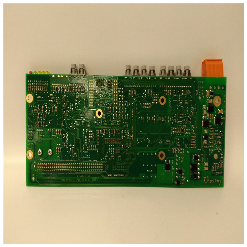
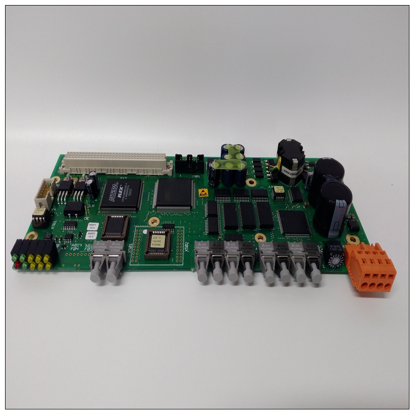
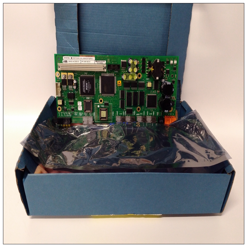
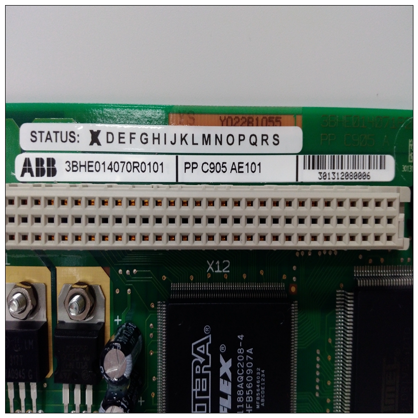
PPC905AE101控制模块,PPC905AE101使用尺寸
模块的输入保护足以保证在性能降低的情况下运行高达200V共模。该模块提供外部电气隔离
通过使用光学隔离在现场布线和背板之间产生噪声。为了将电容性负载和噪声降至最低,模块的所有现场连接应使用优质绞合屏蔽仪表电缆接线。防护罩可以是连接到COM或GND。COM连接提供对模块中的模拟电路。接地连接提供对基板(框架)的访问接地)。
")
PPC905AE101控制模块当模块的电源工作时,面板顶部的LED亮起。主要模块的电源是由PLC电源提供的隔离+24 VDC电源。该电压通过逆变器/调节器传输,为模块提供工作电压。该模块还消耗PLC电源+5 VDC输出的电力,以驱动隔离电路。该模块可以安装在90-30系列PLC系统。见第3-11页,以确定模拟电流输入的数量可以安装在系统中的模块为了限制共模电压,每个电流源公共线可以如果信源是浮动的,也要绑定到其相关的COM终端。这些可选连接如上图所示。有关接线和屏蔽接地连接的详细信息,请参阅第2章。默认范围为4至20 mA,用户数据按比例缩放,使4 mA对应于0计数20 mA对应32000个计数,每1000个计数代表0.5 mA。什么时候在输入/输出端子板上添加跳线,输入范围随用户更改为0至20 mA对数据进行缩放,使0 mA对应于0的计数,20 mA对应于0的计数32000,每800个计数代表0.5 mA。随附两个范围跳线单元一个用于通道1和2,另一个用于通道3和4。
Input protection for the module is sufficient to guarantee operation with reduced performance
with up to 200V common-mode. The module provides electrical isolation of externally
generated noise between field wiring and the backplane through the use of optical isolation.
To minimize the capacitive loading and noise, all field connections to the module should be
wired using a good grade of twisted, shielded instrumentation cable. The shields can be
connected to either COM or GND. The COM connection provides access to the common of the
analog circuitry in the module. The GND connection provides access to the baseplate (frame
ground).
An LED at the top of the faceplate is ON when the module’s power supply is operating. The main
power source for the module is the isolated +24 VDC power supplied by the PLC power supply.
This voltage is routed through an inverter/regulator to provide the operating voltage for the module.
This module also consumes power from the +5 VDC output of the PLC power supply to drive the
isolation circuitry. This module can be installed in any I/O slot of a 5 or 10-slot baseplate in a
Series 90-30 PLC system. See page 3-11 to determine the number of Analog Current Input
modules that can be installed in a systemIn order to limit common-mode voltages, each current source common line may
also be tied to its associated COM terminal if the source is floating. These
optional connections are shown in the figure above.
Please refer to Chapter 2 for wiring and shield ground connection details.The default range is 4 to 20 mA with user data scaled so that 4 mA corresponds to a count of 0
and 20 mA corresponds to a count of 32000 with each 1000 counts representing 0.5 mA. When
a jumper is added to the I/O terminal board, the input range is changed to 0 to 20 mA with user

