


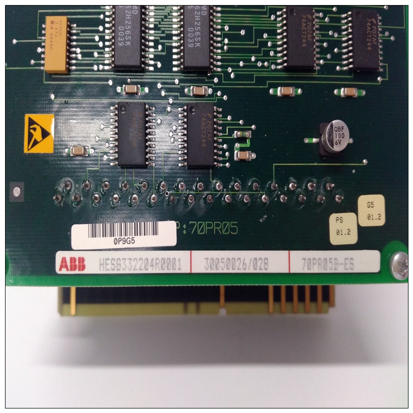
HESG332204R0001卡件70PR05B-ES中文使用说明
双列直插式开关S1的一极将IMHSS03模块置于诊断模式(见图6-2)。第八杆到第五杆双列直插式开关S2选择要运行的诊断测试。第八杆是最低有效位(二进制权重1),第五位是最高的有效位(二进制权重8)。测试ID范围从零到九测试ID值见表6-1。
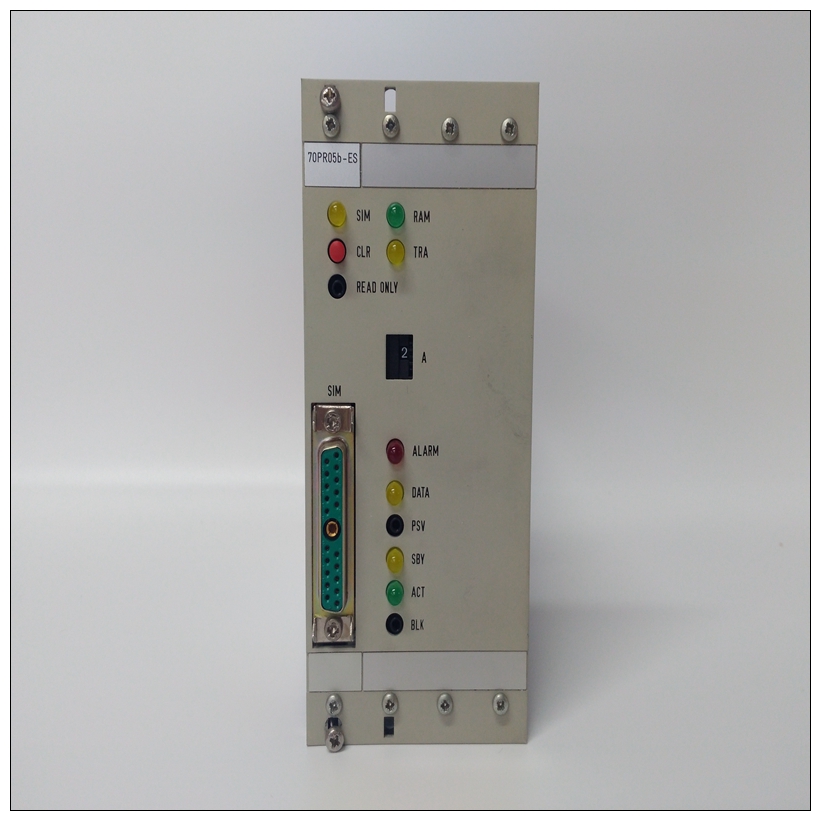
双列直插式开关S2的第一极选择LED显示模式。这个通过/失败模式显示递增通过的组合和故障计数器。LED 1到4表示数字已成功完成个过程。LED 5到8显示故障数(见图6-1)。
")
HESG332204R0001卡件测试编号模式(双列直插式开关S2的第一极)显示LED 1至4上的诊断测试编号。LED五个到七不使用;LED 8为故障LED。测试测试的编号和通过/失败状态显示在测试完成(或失败)。仅显示通过测试测试编号。失败的测试也会打开LED 8以指示失败。双列直插式双列直插式开关S2的第二极选择错误暂停功能。在里面在该模式下,当所选测试检测到错误时,IMHSS03模块将停止测试执行。失败测试的数量显示在IMHSS03 LED上。前面板LED在诊断模式操作期间用于显示测试结果。模块复位时,所有八个LED照明接下来,读取双列直插式开关,选择测试执行,结果显示在LED上。格式LED显示屏的亮度取决于双列直插式开关S2的设置第一杆。如果该极设置为零(on),则测试编号在LED 1到4上显示。如果测试失败。测试将重复。如果S2极1设置为1(关),a成功和失败的运行记录将显示在LED。LED 1到4记录通过,LED 5通过八次故障(见图6-1)。如果测试失败选择错误时暂停(S2,第二极打开),状态LED亮起显示测试状态后为红色。
Pole one of dipswitch S1 puts the IMHSS03 module into diag
nostic mode (see Figure 6-2). Poles eight through five of
dipswitch S2 select the diagnostic test to run. Pole eight is the
least significant bit (binary weight one), pole five is the most
significant bit (binary weight eight). Test IDs range from zero to
nine. Refer to Table 6-1 for test ID values.
Pole one of dipswitch S2 selects the LED display mode. The
pass/fail mode displays a composite of the incrementing pass
and fail counters. LEDs one through four indicate the number
of passes successfully completed. LEDs five through eight dis
play the number of failures (see Figure 6-1).
The test number mode (pole one of dipswitch S2) displays the
diagnostic test number on LEDs one through four. LEDs five
through seven are not used; LED eight is the fail LED. The test
number and the pass/fail status of the test is displayed upon
completion (or failure) of the test. A passing test displays only
the test number. A failing test also turns LED eight on to indi
cate a failure.
Pole two of dipswitch S2 selects the halt on error feature. In
this mode, the IMHSS03 module will halt test execution when
ever the selected test detects an error. The number of the fail
ing test is displayed on the IMHSS03 LEDs.
The front panel LEDs are used during diagnostic mode opera
tion to display test results. On module reset, all eight LEDs
illuminate. Next, the dipswitches are read, the selected test is
executed and the result is displayed on the LEDs. The format
of the LED display depends upon the setting of dipswitch S2
pole one. If this pole is set to zero (on), the test number is dis
played on LEDs one through four. LED eight illuminates if the
test fails. The test will repeat. If S2 pole one is set to one (off), a
running tally of successes and failures will be displayed on the
LEDs. LEDs one through four tally the passes, LEDs five
through eight the failures (see Figure 6-1). If a test fails with
halt-on error selected (S2, pole two on), the status LED turns
red after the test status is displayed.

