


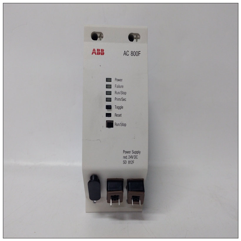
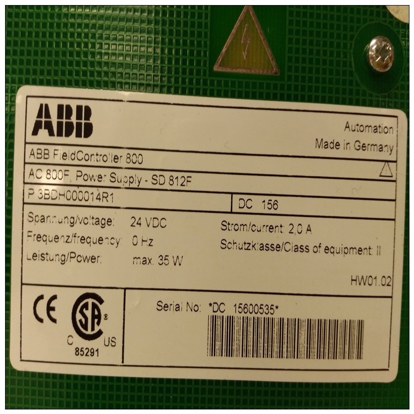
SD812F模块,说明书SD812F
HSS模块使用16位微处理器控制板功能,并通过输入/输出扩展器总线接口。微处理器控制模数处理,将位置反馈和sta 2; tus信息传递给MFP模块,从中读取控制数据MFP模块将位置需求写入D/A转换器并进行自检。
微处理器还控制硬手动电路。这电路提供用户连接到24 VDC的隔离触点,为操作员提供启动液压控制的方法如果MFP模块通信丢失,则执行器。
通过激活升高或降低触点,操作员告知微处理器改变执行器位置。微处理器还写入数字输出,告诉操作员模块处于硬手动操作模式。
")
SD812F模块位置需求和输出位置需求和输出模块包括四个部分:
•D/A转换器。
•位置误差。
•伺服放大器。
•抖动振荡器。
输出电路提供比例积分整个伺服阀的微分(PID)闭环控制系统此外,微处理器读取伺服状态并通过该输出块选择要输出到的伺服。
图2-3显示了职位需求的简化图和输出电路。
The HSS module uses a 16-bit microprocessor to control board
functions and communicate with the MFP module through the
I/O expander bus interface. The microprocessor controls the
analog-to-digital processing, passes position feedback and sta
tus information to the MFP module, reads control data from
the MFP module, writes position demands to the D/A converter
and does self checks.
The microprocessor also controls the hard manual circuit. This
circuit provides isolated contacts the user connects to 24 VDC,
giving the operator a way to initiate control of the hydraulic
actuator in the event the MFP module communications is lost.
By activating the raise or lower contacts, the operator tells the
microprocessor to change the actuator position. The micropro
cessor also writes to a digital output to tell the operator the
module is in the hard manual mode of operation.
Position Demand and Output
There are four parts to the position demand and output block:
•
D/A converter.
•
Position error.
•
Servo amplifier.
•
Dither oscillator.
The output circuit provides proportional plus integral plus
derivative (PID) closed loop control on the entire servo valve
system. Additionally, the microprocessor reads servo status
and selects which servo to output to through this output block.
Figure 2-3 shows a simplified diagram of the position demand
and output circuit.

