3BSE032401R1模块控制卡件,ABB说明书文档
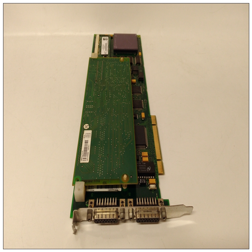
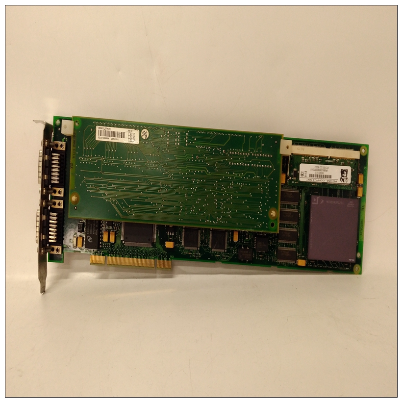
驱动调节由调节器板上的微处理器执行。看见图2.9、2.10和2.11。驱动操作由输入的参数进行调整通过键盘。调节器板接受电源电路反馈信号外部速度参考信号,以及来自连接到的编码器的数据
设置FVC调节时的电机。调节器板提供:
•IGBT功率设备的PWM选通信号根据控制回路的输出,调节器发送PWM选通信号通过电流反馈板至闸门驱动板上的隔离驱动器。
这些驱动器切换绝缘栅双极晶体管(IGBT),产生与速度(FVC调节)或频率(V/Hz)相对应的PWM波形法规)参考。IGBT可在2、4或8 kHz载波下切换频率
")
3BSE032401R1模块控制卡件•驱动器状态指示灯的表A和B触点表格A和B触点由用户通过可编程参数。表格A或B转换可指示驱动器状态。联系人为额定为250 VAC/30 VDC下的5安培电阻负载,可通过端子排。
•四字符显示屏和十四个指示灯LED的显示数据有关键盘/显示器的说明,请参阅第2.8.6节。用于操作说明,请参阅GV3000/SE软件参考手册(D2-3359)。
•模拟输出模拟输出为标度电压(0-10 VDC)或电流(4-20 mA)信号与电机转速(RPM)或电机扭矩或电流(扭矩%)成比例。电流信号选择(通过跨接导线J17)需要电源才能工作。
电源可从编码器端子(4和9)或外部15V电源。详见表7.3和7.8端子10和11信息模拟输出信号可通过端子板获得。
3BSE032401R1模块控制卡件•缓冲电阻器制动信号1-60 HP调节器板提供供可选缓冲器使用的信号用于1-10 HP驱动器的电阻器制动套件。信号可通过终端获得带GV3000/SE驱动器上使用三个调节器板:
•1-60 HP调节板与1-60 HP驱动器一起使用(M/N 1V4XXX至60G4XXX)
•60-150 HP调节板与60-150 HP驱动器一起使用(M/N 75R4XXX至125R4XXX)
•200-400 HP调节板与200-400 HP驱动器一起使用(M/N 200V4XXX至400V4XXX)。
如图2.9、2.10和2.11所示,调节器板相似,但具有不同的电源模块接口连接器。
Regulator Board Description
Drive regulation is performed by a microprocessor on the Regulator board. See
figures 2.9, 2.10, and 2.11. Drive operation is adjusted by the parameters entered
through the keypad. The Regulator board accepts power circuit feedback signals and
an external speed reference signal, as well as data from an encoder that is attached to
the motor when set up for FVC regulation. The Regulator board provides:
•
PWM gating signals to the IGBT power devices
Based on the output of the control loop, the regulator sends PWM gating signals
through the Current Feedback board to isolated drivers on the Gate Driver board.
These drivers switch the Insulated Gate Bi-polar Transistors (IGBTs), producing a
PWM waveform that corresponds to the speed (FVC regulation) or frequency (V/Hz
regulation) reference. The IGBTs can be switched at either a 2, 4, or 8 kHz carrier
frequency.
•
Form A and B contacts for drive status indicators
The Form A and B contacts are under control of the user via programmable
parameters. A Form A or B transition can indicate drive status. The contacts are
rated for 5 amps resistive load at 250 VAC/ 30 VDC and are made available through
the terminal strip.
•
Display data for a four-character display and fourteen indicator LEDs
For a description of the keypad/display, refer to section 2.8.6. For operational
instructions, see the GV3000/SE software reference manual (D2-3359).
•
An analog output
The analog output is a scaled voltage (0-10 VDC) or current (4-20 mA) signal
proportional to either motor speed (RPM) or motor torque or current (%TORQUE).
The current signal selection (via jumper J17) requires a power supply for operation.
The power can be sourced from the encoder terminals (4 and 9) or from an external
15V power supply. See tables 7.3 and 7.8, terminals 10 and 11, for more
information. The analog output signal is available through the terminal strip.
•
A snubber resistor braking signal
The 1-60 HP Regulator board provides a signal for use by an optional snubber
resistor braking kit for 1-10 HP drives. The signal is available through the terminal
strip.
Three Regulator boards are used on the GV3000/SE drives:
•
1-60 HP Regulator boards are used with 1-60 HP drives (M/N 1V4XXX to
60G4XXX)
•
60-150 HP Regulator boards are used with 60-150 HP drives (M/N 75R4XXX to
125R4XXX)
•
200-400 HP Regulator boards are used with 200-400 HP drives (M/N 200V4XXX to
400V4XXX).
As shown in figures 2.9, 2.10, and 2.11, the Regulator boards are similar but have
different Power Module interface connectors.